(THEORY)
(DESIGN)
(MODULES)
(ASSEMBLY)
(OPERATION)
(ARM DSP)
(HOME)
Vertical Navigation Radar
Matjaz Vidmar, S53MV
1. Theory
Although aviation radar altimeters were developed and successfully installed on different types of aircraft before the second world war, this instrument never found widespread use in general aviation. Today civilian radar altimeters are only installed on large airliners and they are only used in the final approach and landing phases of flight. On the other hand, the same reliable and inexpensive radar technology could provide many benefits to general aviation and in particular to small aircraft operating in VFR.
An excellent example in maritime sonar. Sonar was first used on military vessels. Of course sonar is used on all large civilian ships too. On the other hand, sonar is a very popular navigation instrument on small leisure boats as well! Although sonar was first intended as a depth finder, today sonar is also used on small leisure boats for many other purposes, like detecting large rocks, fish formations or ship wrecks on the sea floor.
An aviation radar altimeter compares directly to a sonar depth finder. A radar altimeter operates in the 4.3GHz frequency band corresponding to an electromagnetic wavelength of about 7cm. A sonar depth finder operates at 200kHz corresponding to an acoustic wavelength of about 0.7cm in sea water. However a small aircraft travels at 100knots or about 10-times faster than a small boat. A small aircraft flies up to 5000feet (1500m) altitude compared to the 500feet (150m) range of a sonar depth finder. Interestingly, all important parameters of radar versus sonar are in an almost exact 10:1 ratio!
Sonar developed into a powerful yet affordable navigation tool even for small boats thanks to the advances in electronic signal processing and comprehensive display of information. The result of the sonar measurement is displayed both graphically and numerically, while additional electronics provides acoustic warnings as well. Many new features were built into maritime sonar thanks to the feedback from a large user community.
There may be many reasons why the same did not happen with aviation radar altimeters, in spite of the similarity to maritime sonar. First, all aviation instruments have to go through a difficult certification process. The user community is much smaller. User feedback is difficult if not impossible. Instrument developers are required to fit into the strict rules of IFR rather than developing the best instrument that a particular technology could offer. Little if any development is done for VFR, in particular to help the VFR pilot when conditions become marginal.
In this article it is proposed to introduce new ways of using an improved radar similar to a radar altimeter on board a small aircraft operating in VFR. New but inexpensive electronic technology allows a significant improvement of the performance, data processing and display of information. A list of required tasks should include at least the following points:
(1) Full assistance in all phases of landing, from the traffic pattern to the final approach and landing flare. The instrument should be fast and accurate to allow a landing in poor visibility. The information should be relayed to the pilot without distracting him from other tasks during the landing.
(2) Ground-proximity warning in all phases of flight. Clear unambiguous synthesized voice messages are required, possibly without false alarms.
(3) VFR aircraft are frequently required to stay below the TMA of a large airport due to commercial IFR traffic. A simple instrument is required to stay below the TMA and maintain a safe altitude at the same time.
(4) VFR aircraft frequently have to stay below a cloud ceiling. A simple instrument is required to find out whether there is enough space between the mountain ridge to be crossed and the cloud ceiling.
(5) VFR conditions may degenerate into Special VFR due to mist. Flying in such conditions is really demanding. A suitable radar altimeter helps the pilot maintaining a safe altitude and obstacle clearance.
(6) Glider pilots look for favorable winds close to mountain ridges. A reliable instrument is required to keep a safe distance from the ridge without known references on the ground.
(7) Glider pilots frequently need a reliable instrument to find out whether their altitude is sufficient to make an un-powered flight to the nearest airport.
(8) An emergency landing requires a quick and reliable instrument to measure the altitude of the aircraft above ground during all phases of the emergency.
(9) An instrument capable of detecting tiny but dangerous obstacles like high-voltage power lines is highly desired.
(10) Night-time flight requires a reliable instrument to maintain terrain and obstacle clearance.
(11) Night-time landings are much safer if the pilot is assisted by a reliable and accurate altimeter, especially during the landing flare.
(12) It is very difficult to estimate the correct altitude for the landing flare on water surfaces, especially on lakes with smooth surface and no known references. Here a reliable and accurate radar altimeter really helps.
(13) Any navigation instrument should remain active and provide useful data during all phases of flight. Therefore the range of a radar altimeter should be sufficient to provide meaningful data as high as practical. Most important, false warnings should be avoided when its maximum range is exceeded.
(14) Any navigation instrument should include self-testing capabilities or better be designed in such a way that any failure is immediately evident to the pilot. The output to the pilot should be such that the latter can establish immediately whether the measured data is useful and trustworthy.
A radar instrument fulfilling many or all of the above requirements can readily be designed and built. Since its capabilities are well beyond those of a conventional radar altimeter, a new name "VERTICAL NAVIGATION RADAR" is given to this new instrument.
In order to use a vertical navigation radar efficiently, the pilot should first understand the operation principles and limitations of such a radar installed on a small aircraft. Therefore the theoretical background is discussed in this section "Theory", including alternate technologies to a 4.3GHz radar. In the second section "Design", the detailed design of such a radar is presented. Individual electronics modules are presented in the third section "Modules", while their assembly and installation is presented in the fourth section "Assembly". Finally, in the last fifth section "Operation" of this article, the alignment, testing and practical operation of the vertical navigation radar is presented.
Due to the limited space on a small aircraft, a radar antenna with a steerable beam (either mechanically or electrically) usually can not be installed. Therefore the radar beam simply points down. The radiation pattern of the radar antenna should be wide enough to allow for the expected pitch and roll of the aircraft. This requires an antenna beam width of more than 70 degrees and an antenna directivity of about 10dBi, as shown on the following illustration:
Different targets reflect radio waves in different ways. Smooth targets like lakes, sea, paved roads and paved runways provide specular reflections. Specular reflections are very strong and are always at right angle. The specular reflection area is defined by the first Fresnel zone, it is usually rather small and it is only dependent on the distance and wavelength. The shape and tilt of the antenna beam does not affect a specular reflection.
Rough targets like bushes, trees, mountains and unpaved runways provide diffused reflections. Diffused reflections are rather weak since the radio signal is scattered in many directions. The diffused reflection area is defined by the antenna radiation pattern. Tilting the antenna changes the reflection area! The reflected signal is random, the reflection intensity obeys the Rayleigh statistics.
In the case of a specular reflection it is relatively simple to measure the altitude of the aircraft above ground. The only disturbing effect may be a double-pass signal reflected from the smooth target, then from the aircraft wings/fuselage and again from the same smooth target. On the other hand, a rough target provides a complex reflected signal as shown on the following illustration:
In the case of a diffused reflection, the first radar return comes from the area just under the aircraft and this is a good estimate for the aircraft altitude. Increasing delays correspond to scatterers at increasing distances from the aircraft. Although the antenna radiation pattern limits the reflecting area, some radar returns come back at delays corresponding to many times the aircraft altitude. Fortunately the intensity decreases rather quickly with distance.
Since a diffused reflection provides a random signal intensity, the accuracy of such a measurement is affected. Considering the radiation pattern of the radar antenna, most of the reflected signals comes back in a time interval that corresponds to about 10% of the measured altitude. Improving the accuracy of a radar altimeter beyond 10% requires averaging many measurements.
A frequent, practical but difficult case for an altimeter is shown on the following illustration:
Objects just under the aircraft (trees and bushes) provide a very weak, diffused reflection. On the other hand, the much more distant house makes a 2D corner reflector with the road, providing a very strong specular reflection exactly in the direction of the aircraft. The situation may be even worse with groups of houses that may form 3D corner reflectors. In fact, towns always appear as very bright spots on satellite radar images!
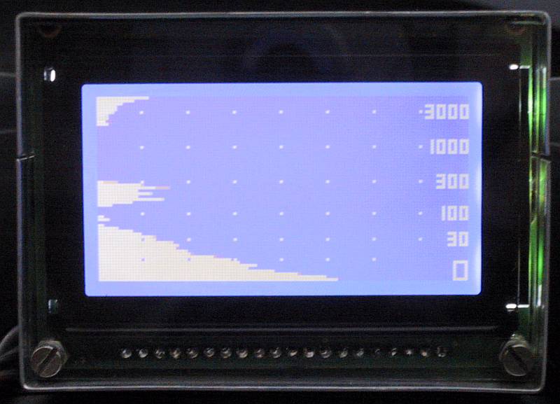
Even distant objects outside the main antenna beam may provide strong reflections and may compromise the operation of a radar altimeter. Besides a very strong reflection from ground and some noise at the maximum range, the radar altimeter of the aircraft parked in front of the hangar also receives a strong reflection from the hangar door:
Although the hangar door is some 100m (330feet) away, its specular reflection outside the antenna beam may corrupt the measurement from ground at just 60cm (2feet) from the radar. Please note that on all pictures and in the following discussion the display axes are reversed: the horizontal axis means intensity and the vertical axis means altitude in a logarithmic scale.
A similar effect takes place while parking the aircraft among other aircraft in front of the hangar (reflections between 100ft and 300ft), as shown on the following close-up picture:
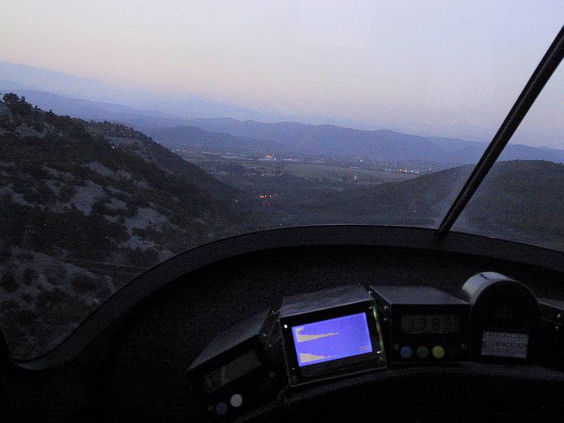
On the other hand, strong specular reflections can be used to detect tiny but dangerous targets like high-voltage power lines, as shown on the following illustration:
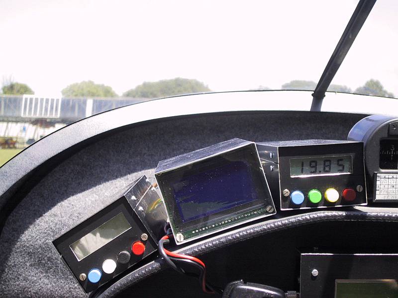
On the following picture the aircraft is flying 500feet above the valley bottom, while the power-line wires are just visible in the left bottom of the windscreen:
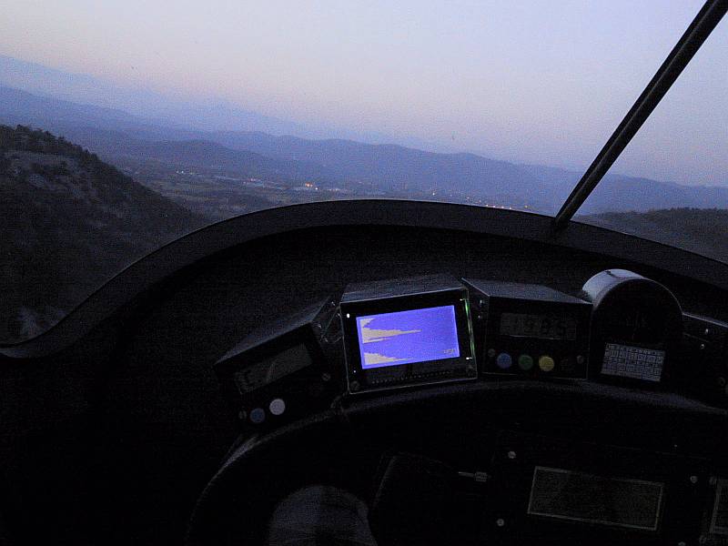
A few seconds later, the aircraft is just above the wires. Besides the reflection from the valley bottom at 450feet, another reflection from the wires is also visible at 250feet:
Of course the above cases are rather extreme. They are shown here to understand the design issues explained in the following section of this article "Design". Many more practical examples are shown in the final section of this article "Operation".
At the end of this theoretical introduction it makes sense to discuss alternative technologies to be used in a vertical-navigation instrument. A landing altimeter could be built as a capacitance meter. This solution is not very practical since electrodes should be installed far apart, for example on the wingtips. Further, each aircraft type would need a special calibration. Finally, the range of a capacitance meter is limited to below 300ft (90m).
Another possibility is to use a sonar on-board an aircraft. Unfortunately air is not such a good medium for the propagation of sound waves as water. Air sonar operates at lower acoustic frequencies where the attenuation of sound waves in air is smaller.
Inexpensive ultrasonic transducers for operation in air are available for 38kHz corresponding to an acoustic wavelength of about 0.8cm in air. At this frequency the practical range of a sonar is less than 10m (33ft). Further, sonar may be disturbed by acoustic noise generated by the air streaming around the aircraft in flight.
Since the acoustic impedance of air is very high due to the low air density (compared to water or solids), 38kHz transducers are highly resonant (usable bandwidth less than 1kHz). For the same reason these transducers are affected by moisture or dirt accumulating on the mechanical resonator. The practical use of sonar is therefore limited to model aircraft and/or small UAVs that only fly low and slow in fine weather and produce little noise.
Finally the radar could also be built in frequency ranges different from the conventional 4.2-4.4GHz radar-altimeter band. In particular, inexpensive automotive-radar hardware may become available for the frequency ranges of 24GHz and 77GHz. Higher frequencies offer a higher accuracy during the landing flare and the possibility of building 2D or even 3D radars with small steerable antennas. On the other hand, all millimeter-wave electronics has to be built directly inside the antennas and the latter are badly affected by dirt or moisture accumulating on their surface.
(THEORY) (DESIGN) (MODULES) (ASSEMBLY) (OPERATION) (ARM DSP) (HOME)