Some electronic modules for the AMSAT P3D satellite
Matjaž Vidmar, S53MV
One of the largest amateur satellite projects was the AMSAT P3D satellite. This satellites included more than 50 electronic modules built by enthusiast engineers all over the world. Besides electronics there were several other devices onboard, including two different rocket engines.
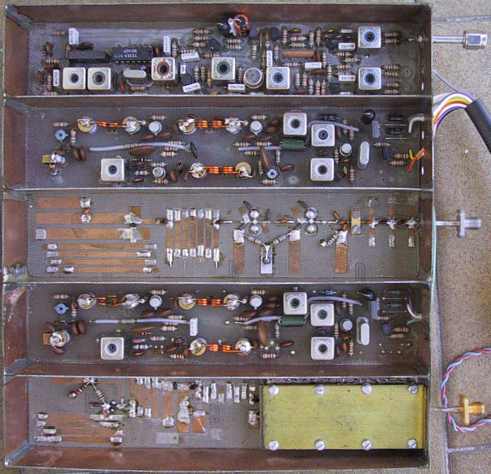
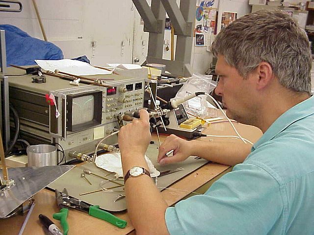
My involvement in the AMSAT P3D project started by building receiver prototypes back in 1993. The prototype on the following picture is a low-noise receiver for 2.4GHz (13cm) and 5.6GHz (6cm), sharing a common IF output at 10.7MHz:
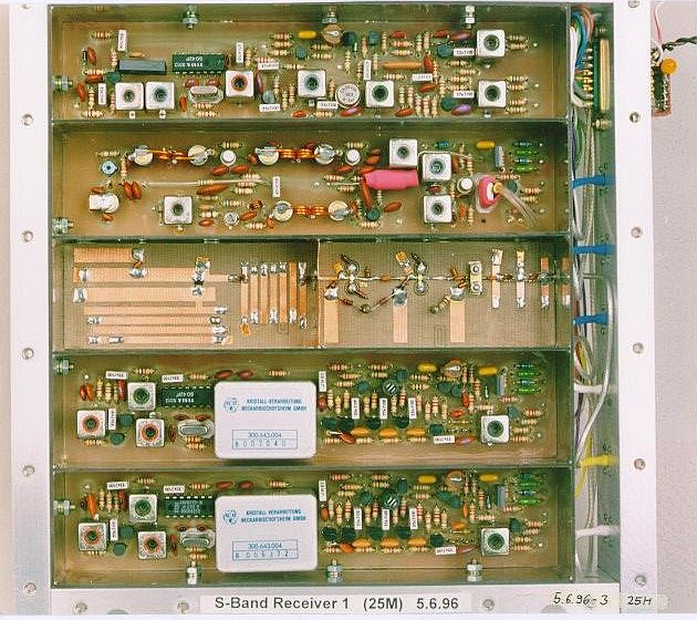
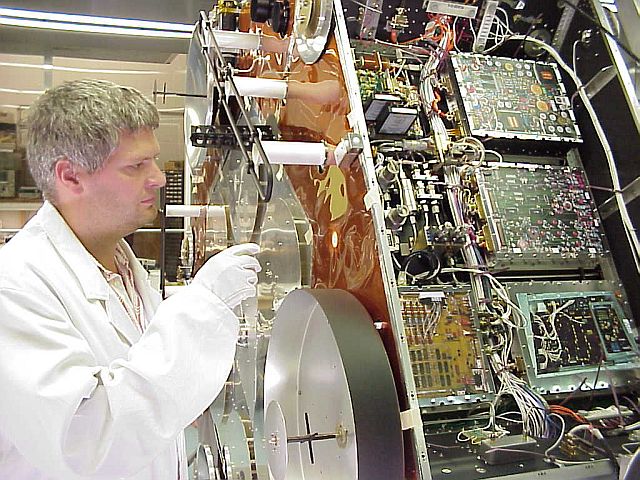
After extensive testing of the prototypes, the final versions of the flight-qualified receivers were built much more carefully. The following picture shows my module with three independent receivers for 21MHz, 24MHz and 2.4GHz:
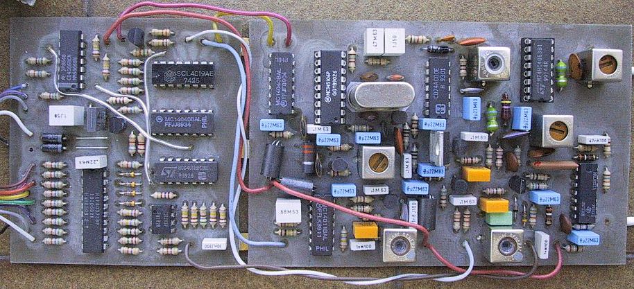
A promised feature of the AMSAT P3D satellite was an IF signal processor (named LEILA) to avoid the abuse of the satellite by high-power uplinks. My prototype was an analog IF processor with a tunable notch filter and jam signal source:
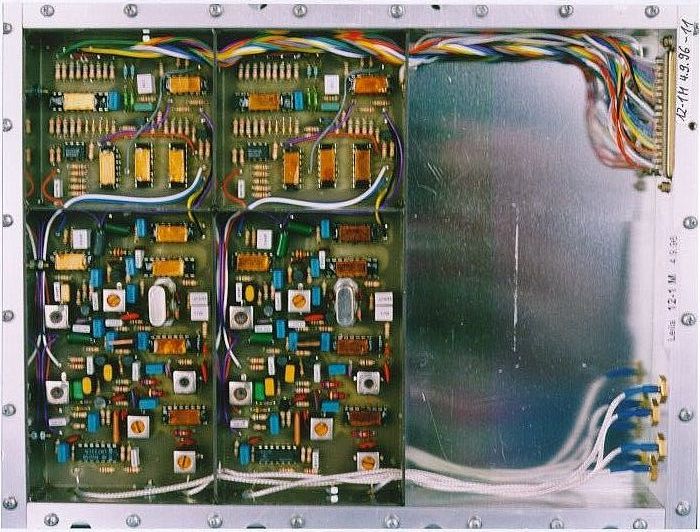
Two identical LEILA IF processors were installed in one module of the AMSAT P3D satellite:
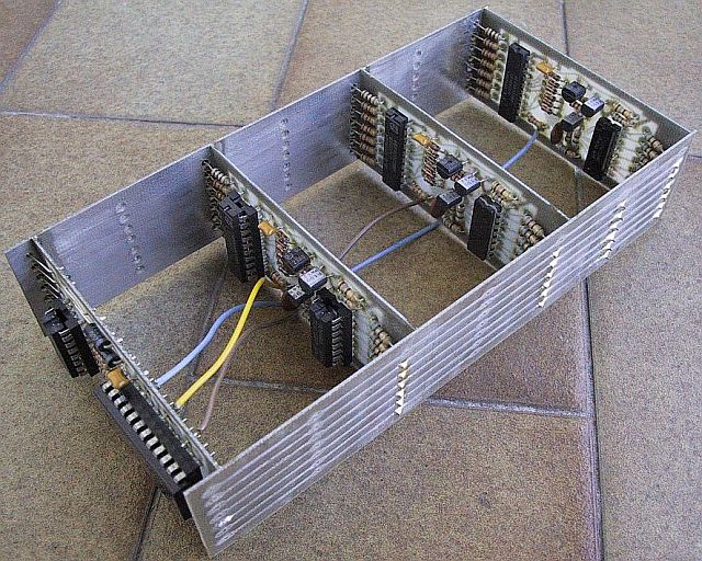
The design of the AMSAT P3D satellite required all receivers, transmitters and other circuits to use a common 10.7MHz IF. A very reliable IF switching matrix was required to route the 10.7MHz IF signals to their correct destinations.
My prototype was a fully additive switching matrix allowing the combination of many different sources to a single destination:
A beacon 10.7MHz IF source was also developed allowing CW, 170Hz FSK and 400bps BPSK modulation:
![]()
Three such beacons were integrated in the flight version of the IF switching matrix with 12 inputs and 7 outputs:
![]()
The IF-switching-matrix module was stacked on top of the LEILA module inside the AMSAT P3D satellite:

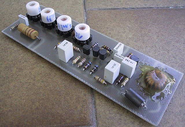
Some other minor electronic modules became necessary further in the design of the satellite. Therefore I developed the following prototype antenna matching circuit to share a single HF monopole among the 21MHz and 24MHz receivers and the "Monitor" HF spectrum analyzer:
Impedance-matching circuits and out-of-band rejection filters were also required for the 2m, 70cm and 24cm omnidirectional antennas:
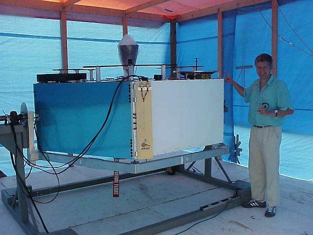
The only way to test all of the RF hardware, including searching for mutual interferences onboard the satellite, was to move the completed AMSAT P3D satellite out of the clean room into a tent:
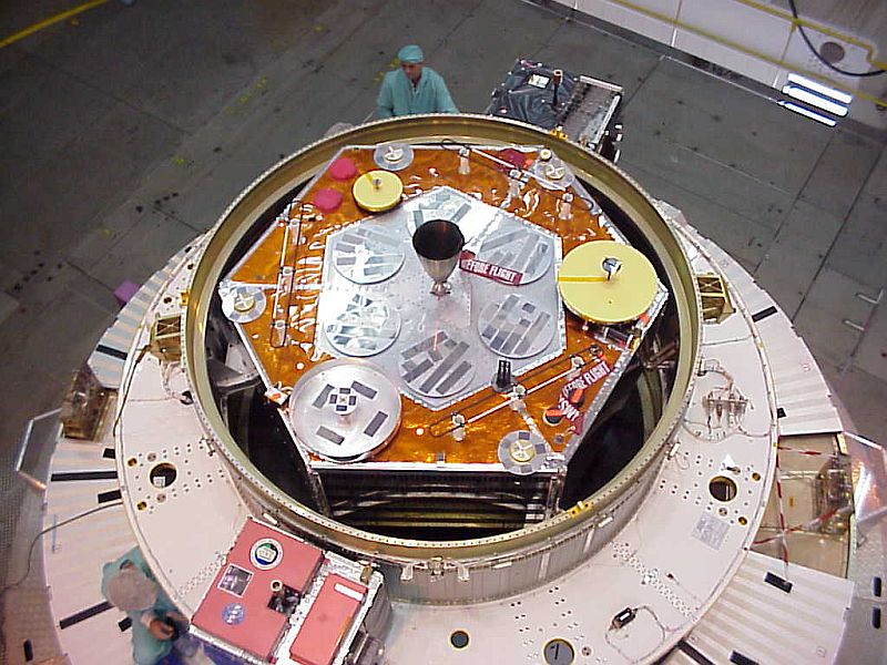
Checking the antennas of AMSAT P3D in the cleanroom in Orlando, Florida, USA:
As a secondary payload, the AMSAT P3D satellite was installed in an adapter ring on top of an Ariane 5 rocket, together with two smaller secondary payloads:
The main payload, a Panamsat PAS 1R communication satellite, was installed on top of the adapter ring. The Ariane 5 rocket was successfully launched on November 13th, 2000.
Unfortunately the AMSAT P3D or AO-40 satellite was severely damaged by an onboard rocket-engine explosion about one month after launch. Therefore not all of the modules I have built could even be tested. However, my IF switching matrix operated flawlessly and both my LEILA IF processors proved effective. Out of all receivers I have built, only the two 2.4GHz receivers could be operated in space for a short period of time.