(ANALOG)
(DESIGN)
(MODULES)
(ASSEMBLY)
(HOME)
ARM DSP Vertical Navigation Radar
Matjaz Vidmar, S53MV
3. Assembly
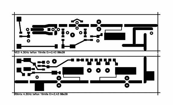
The assembly of the ARM DSP Vertical Navigation Radar should start with the most critical microwave modules, described in the previous section "Modules". Both the transmitter and receiver microwave sections are built as microstrip circuits on double-sided teflon laminate with a dielectric constant of 2.43 and 19mils (0.5mm) thickness. The top side is shown on the following illustration while the bottom side is not etched to act as a ground plane:
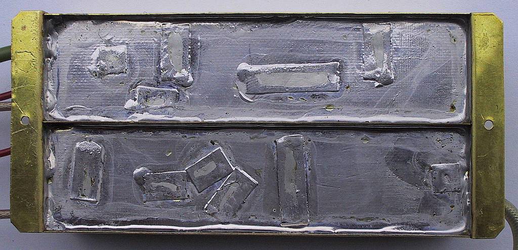
The two microwave modules are soldered into a frame made from 0.3mm thick brass sheet. The frame includes mounting lugs and holes for feed-through capacitors as well as coaxial cables, as shown on the following image:
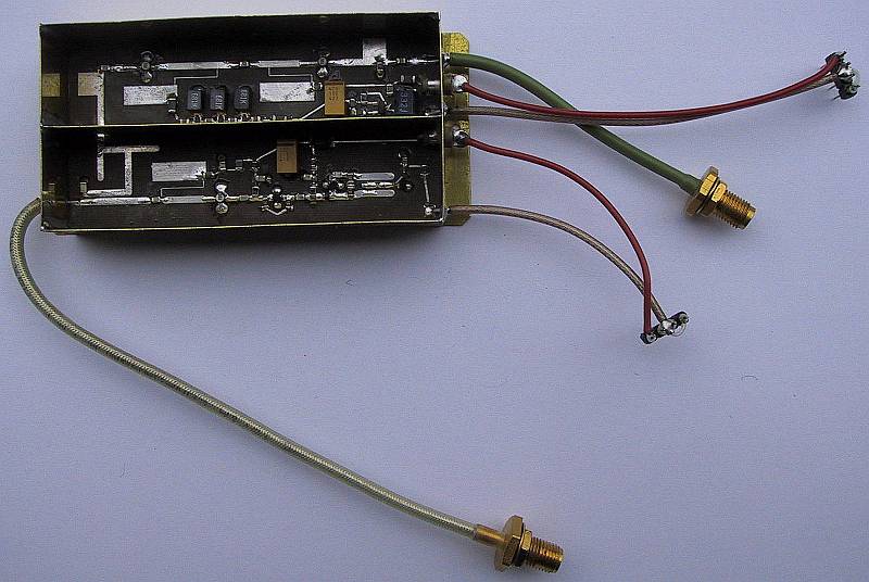
Finally, the assembled RF front end is equipped with cables and connectors. All coaxial cables have teflon insulation so that their shielding can be soldered directly to the brass frame. All supply connections go through feed-through capacitor, as shown on the following image:
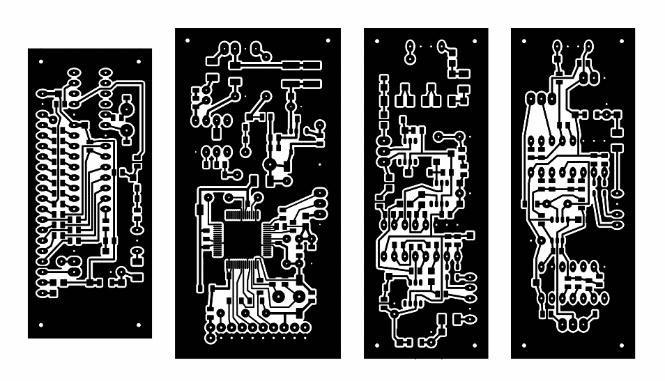
The remaining four modules are built on four conventional, single-sided printed circuit boards, etched on 1mm-thick FR4 laminate with 17.5 micrometer copper cladding. All SMD components are installed on the bottom side while components with wire leads are installed on the top side. The circuit board patterns are shown on the following illustration:
The original PCB files and all software including source code and voice recordings are available in the following archive:
PCB files, compiled software, source & voice

The completed modules are installed in an aluminum case. The latter includes a central frame and backplate made from 1mm-thick aluminum sheet, top and bottom covers made from 0.6mm-thick aluminum sheet and a front plate made from 2.5mm-thick plexiglass. The size of the box is selected to fit the dimensions of the graphical LCD module 53mmX75mm.
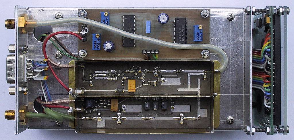
The sweep module and the microwave front-end are installed on the bottom side as shown with covers and absorber removed on the following image:
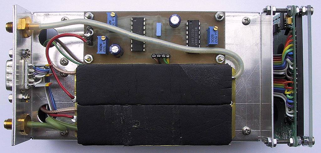
Microwave absorber foam is installed on top of both microwave modules. No further shielding is required for the microwave front-end. The microwave absorber suppresses unwanted resonances and thus improves the linearity of the VCO, which in turn improves the resolution of the radar. The installation of 1cm-thick absorber foam is shown on the following image:
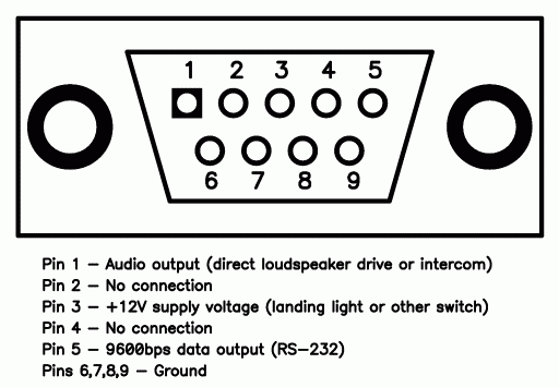
Two female SMA connectors are used for the receive and transmit antennas. The power supply, the RS-232 output and the audio output go to a male DB9 connector. Three 470pF capacitors are installed on this connector to block interference from other radio transmitters (in particular the VHF two-way radio) on-board the aircraft. The pin assignments of the DB9 connector are shown on the following drawing:
The nominal supply voltage is 12V to 14V DC, negative grounded. The current drain of the complete instrument is around 265mA, including the LCD backlight but with the voice synthesizer inactive. The power drain can grow up to 500mA when actively driving a low-impedance loudspeaker.
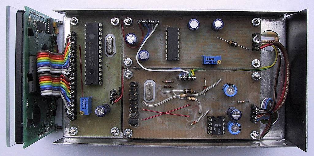
The remaining three modules: the IF module, the main-processor module and the LCD module are installed on the top side, as shown with covers removed on the following image:
All four single-sided printed-circuit boards are installed using four M2.5 screws in each corner. Two additional long M2.5 screws are used to hold the front plate and LCD module.
The complete instrument installed in the described aluminum case weights around 330grams. A pair of 4.3GHz antennas as described together with the previous ANALOG Vertical Navigation Radar weights 135grams. Two antenna cables, supply and audio wiring weight another 250grams. The total weight of the installed instrument is therefore around 715grams.
The new ARM DSP Vertical Navigation Radar can be used with almost any pair of linearly-polarized 4.3GHz radio-altimeter antennas. Small differences in the antenna gains and cable losses can be compensated with the trimmer in the IF module. Like for the ANALOG Vertical Navigation Radar, the antennas should be oriented for TE polarization and kept at sufficient spacing to limit unwanted crosstalk.
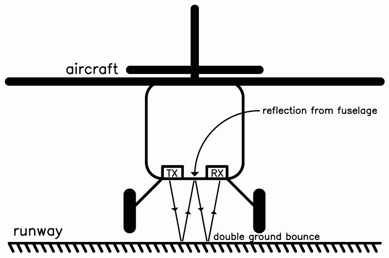
Depending on the height of the aircraft landing gear, the cable lengths to the two antennas may need adjustments to calibrate the radar at low altitudes. Unwanted reflections from the fuselage may cause double-pass errors, especially at very low altitudes (usually less than one foot), like explained on the following drawing:
Depending on the installation of the antennas, the antenna cables may not reach the instrument panel. In this case it makes sense to install most of the electronics of the ARM DSP Vertical Navigation Radar close to the antennas. The LCD controller and the LCD module itself can be installed separately, since the interface includes only three wires: serial 9600bps data, +12V supply and ground.
The 9600bps RS-232 output can drive in parallel other display devices as well. The data format is start bit, 8 data bits, no parity and two stop bits. The frame format is explained on the following drawing:
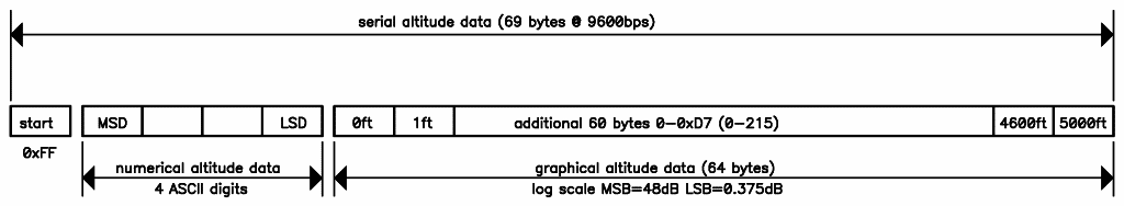
Data frames are transmitted as frequently as possible by the main-processor module. The 0xFF character is used as a synchronization character and as a start-of-frame marker and it is not allowed to appear anywhere else in the data frame. The LCD module controller is programmed to invert the polarity of the display if no valid data is received for a few seconds.
The ARM JTAG connector on the main-processor module is used to program the LPC2148 FLASH with a suitable programmer. During normal operation of the instrument, the same connector is used to select some operating parameters by installing jumpers as shown on the following drawing:
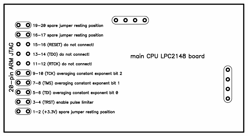
All active JTAG pins have internal pull-up resistors inside the LPC2148. Pins TRST, TDI, TMS and TCK can be shorted to ground without affecting the function of these and/or other LPC2148 pins. A grounding jumper on TRST will enable the pulse limiter. The latter effectively removes pulsed interference from the ATC transponder or DME. On the other hand, the limiter slightly distorts useful data and increases processing time.
Grounding jumpers on TDI, TMS and TCK will select the amount of data averaging in eight binary exponential steps 0...7. Averaging can be turned off completely (0) by omitting all three jumpers. Usual setting is 4 or TCK shorted to ground while TDI and TMS are left open. Spare jumpers can be left on unused pin pairs 1-2, 17-18 and/or 19-20.
The calibration, regular checks and operation of the new ARM DSP Vertical Navigation Radar are almost identical to the already described ANALOG version. Of course, the new DSP instrument provides improved speed, accuracy and reliability when compared to the old ANALOG version.
The only major difference is the signal-level threshold adjustment in the old version. The threshold is set permanently to the display center in the new version. A much better solution is to adjust the IF gain to compensate for different antenna gains, cable losses or other component tolerances.
The display amplitude range has been reduced from 55dB in the old version to 48dB in the new version. In this way both the antenna crosstalk at low altitudes and the thermal noise at the highest altitudes are less annoying for the user but still visible for an immediate operational check. The 10 bit A/D converter inside the LPC2148 is quite noisy and it lacks sample-&-hold circuits, causing some additional artifacts on the display. Fortunately these imperfections of the LPC2148 A/D converter do not affect the accuracy of the altitude measurements.
Further improvements of the speed, accuracy and reliability of a radio altimeter or vertical navigation radar are rather limited. A quadrature receiver could bring some improvement at low altitudes. The same design with the same accuracy could be shifted to the 5.6GHz ISM frequency band if the 4.3GHz (certified) altimeter band is not available. Unfortunately about the same bandwidth is available in both bands resulting in the same expected accuracy. Worst of all, improperly-mated (poor-quality or damaged) SMA connectors have a resonance around 5.6GHz disrupting the operation of a precise instrument like a radar.
Much higher accuracy could be obtained by using automotive-FM-radar modules operating at 77GHz. The latter could improve the accuracy to about one inch (a few centimeters), but the maximum range may be restricted to less than 300 feet (100 meters). The antennas of these modules may be very sensitive to dirt and moisture impairing the reliability of the instrument.
Finally, synthetic-aperture-radar (SAR) techniques could be applied to the same FM-radar hardware (antennas and microwave front end) to measure the terrain profile in the direction of movement (flight). Such a two-dimensional Vertical Navigation Radar is an interesting research topic that requires even more signal processing. Last but not least, a method to conveniently represent the results of such measurements has yet to be invented.