(HISTORY)
(COUNTER)
(FRONTENDS)
(PROBES)
(ASSEMBLY)
(OPERATION)
(HOME)
Simple RF/Microwave Frequency Counter
Matjaz Vidmar, S53MV
1. History
Time and frequency are certainly the physical quantities that can be measured with the highest accuracy. Precise frequencies are also required in radio communications. Radio technology, including amateur-radio technology, started measuring frequencies with different kinds of absorption wave-meters. The most popular instrument among amateurs was certainly the grid-dip meter. The latter was only accurate enough at relatively low frequencies (below 30MHz) and with wide modulation formats (like AM voice).
Digital frequency counters could be built with vacuum tubes. Some specialized vacuum tubes, like the Philips E1T decade counter tube, included all counting and display hardware for one complete counting decade. Unfortunately all vacuum-tube counters as well as germanium-transistor flip-flops and early integrated-logic families were not fast enough to allow direct counting at practical frequencies used in radio communications.
A major breakthrough was represented by the TTL logic family. Inexpensive TTL chips became widely available around 1970 and allowed counting frequencies up to about 40MHz. Accurate digital frequency counters were finally within reach of all radio users including amateurs. Cheap LED displays became available just a few years later replacing expensive "nixie" display tubes and their associated high-voltage supplies. A 40MHz counter is more than adequate for any work at HF and can measure the frequencies of most crystal oscillators that are afterwards multiplied to the VHF or UHF frequency range.
I built my first frequency counter as a high-school student in just one weekend back in 1976. TTL chips were not available locally yet. My father brought me a few 7490 decade counters, a few 7447 7-digit decoders and a 1MHz reference crystal from West Germany. I remember that my father came home from his business trip on Friday evening while the counter was fully functional on Sunday evening on the same weekend! Finally I could find out where did the crystals of my homemade radios multiply in the 144MHz band...
Counting faster than the 40 or 50MHz allowed by the inexpensive TTL circuits was considered very expensive. Most amateur counters used expensive ECL decade counters: the 95H90 allowed reaching 300MHz while the 11C90 counted up to 600MHz. Finally around 1980 inexpensive ECL prescalers became available for frequency synthesizers of TV sets. Of course I upgraded my counter with one of the first such cheap prescalers, the Siemens S0436, reliably counting up to 1.4GHz!
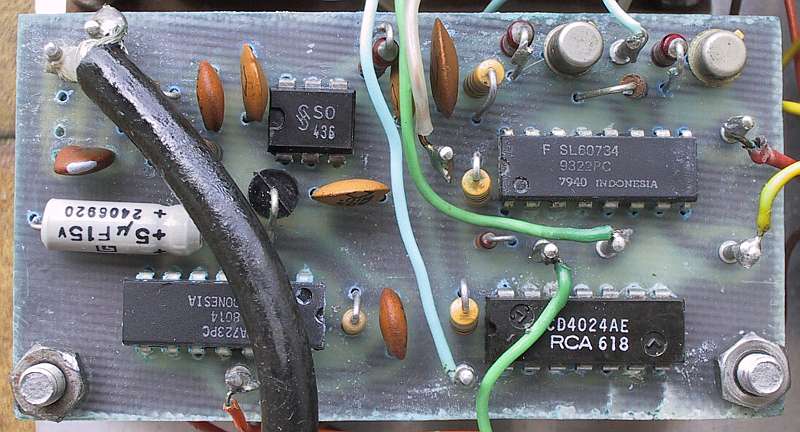
The S0436 was not easy to use. Besides a nonstandard supply voltage of +6.8V and a nonstandard ECL output, this device divided the input frequency by 64. A rather simple solution was to divide the reference frequency of the counter gate by the same modulo 64 with a slow and cheap CMOS divider 4024. A single fast-switching transistor shifted the nonstandard ECL (CML) output of the S0436 to standard TTL signal levels.
Measuring frequencies much above 1GHz was still a difficult task. For example, receiving converters for satellite TV operating in the 4GHz and 11GHz bands used free-running oscillators at the final frequency making digital counters almost useless. Therefore the simplest absorption wave-meter was built, the famous Lecher wires. The Lecher wires include a section of parallel-wire transmission line and a moving short. The latter forms a half-wave resonator with the shorted end of the transmission line.
The shorted end of the transmission line is inductively coupled to the circuit under test, usually a microstrip resonator. When in resonance, the Lecher wires absorb some microwave power out of the circuit under test causing a measurable dip with a separate detector somewhere in the test circuit. The position of the first dip is not very accurate, the relative positions of the following dips are however very accurate.
The Lecher wires do not require any calibration except for measuring the positions of the dips. If an 1m long welding electrode is bent into 50cm long Lecher wires, this simple instrument can roughly measure frequencies above 300MHz and much more accurately above 600MHz. It makes sense to terminate the open end of the Lecher wires with a 270ohm resistor to avoid unwanted resonances.
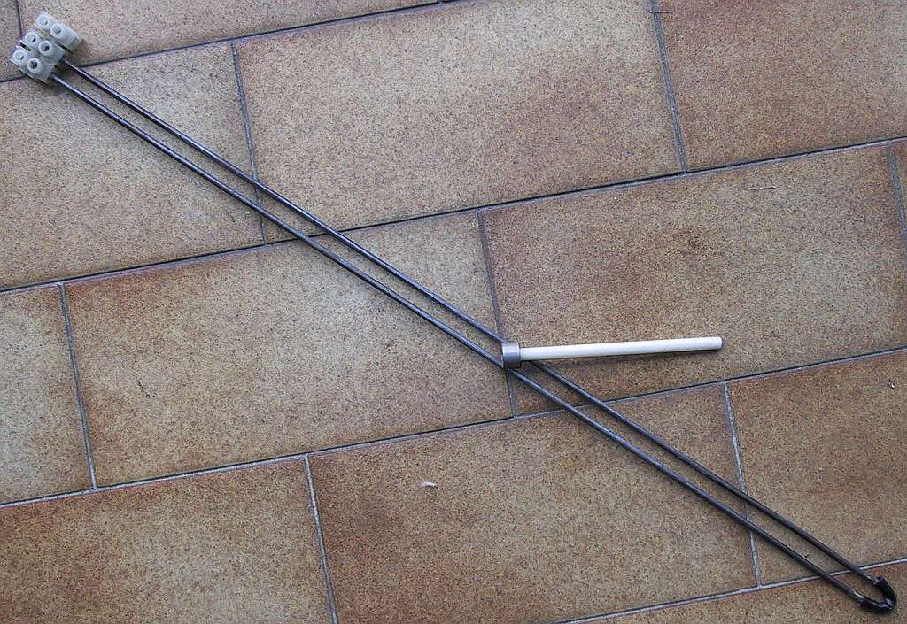
The frequency range and accuracy of the Lecher wires is really surprising. The simple and rude instrument shown on the photo is able to measure frequencies beyond 10GHz with an accuracy better than 1% by counting several consecutive dips and measuring the distance between the first dip and last dip!
Professional microwave frequency counters are built as heterodyne receivers. The input signal is fed to a harmonic mixer and down-converted to a much lower intermediate frequency. The counter measures the local-oscillator frequency, multiplied by the appropriate harmonic number and adds or subtracts the resulting intermediate frequency. In this way both the LO and IF are well within the range of conventional digital counters.
Such a counter needs additional processing to find the harmonic multiplier and the sign of the resulting intermediate frequency. This information can be obtained by frequency modulating the LO and measuring the magnitude and phase of the FM deviation on the resulting IF.
I built such an experimental microwave counter back in 1982. All of the signal processing was done without any microprocessor, using just analog electronics and hardwired TTL logic! The local oscillator operated between 400MHz and 900MHz, well within the capabilities of the S0436 prescaler. This frequency counter eventually reached 6GHz but unfortunately its operation was quite unreliable. Therefore I decided not to publish its detailed circuit diagrams.
While digital volt-meters, ampere-meters and ohm-meters quickly became small and inexpensive hand-held instruments, digital frequency counters remained large and expensive laboratory equipment for many years. There were just a few attempts to market simple and inexpensive hand-held frequency counters. One such device was the hand-held frequency counter distributed by Radio Shack around 1997.
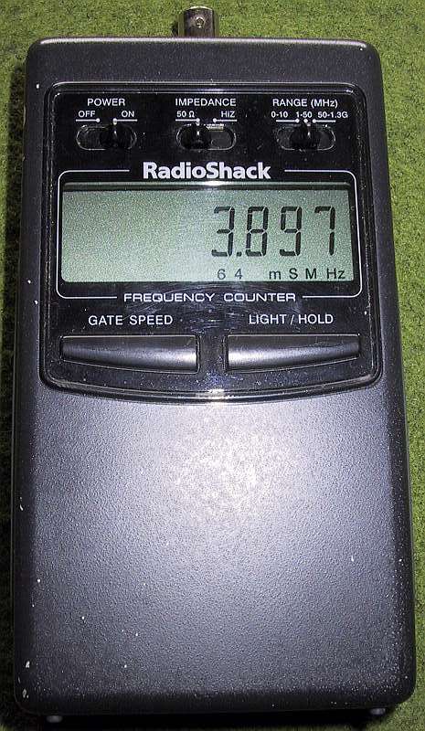
The Radio-Shack hand-held counter was really well designed. It included three different input stages, precisely matching the needs of an engineer: a low-frequency TTL input, a sensitive RF input and a microwave input specified to 1.3GHz but operating correctly well beyond 2GHz. Unfortunately this counter was offered with the wrong probe (a small telescopic antenna) to the wrong public. My unit is still running great after ten years. During this period it helped solving many problems in the field, of course using appropriate probes!
Does it still make sense and how to design a frequency counter today in 2007? The MC10ELxx and MC100ELxx logic families have been around for many years allowing direct counters up to at least 2GHz. Similar SiGe logic families introduced recently allow operation beyond 8GHz. Analog frequency dividers can be built from readily-available components for frequencies beyond 10GHz [1] although it is much simpler to use readily-available prescalers [2].
Microprocessors with integrated memory and peripherals certainly allow a substantial simplification of the hardware. On the other hand, one has to be very careful to avoid some useless features available with microprocessors like automatic switching between frequency and period counting or automatic input level and threshold adjustments. These "features" may work correctly in some instances while corrupting the measurements in other cases, like non-periodic or random signals or signals with extreme duty cycles far away from 50%.
Considering the accuracy of the available reference frequency, a direct counter is required up to 50MHz...200MHz. This figure matches the lowest frequency accepted by most microwave prescalers. Of course, binary-modulo prescalers like /64, /128, /256 etc can simply be used by multiplying the counter-gate period by the same number inside the microprocessor software. This is a much better solution than the pulse-swallow counters used to obtain decimal-division ratios with binary-modulo prescalers, but causing additional jitter on the measurements.
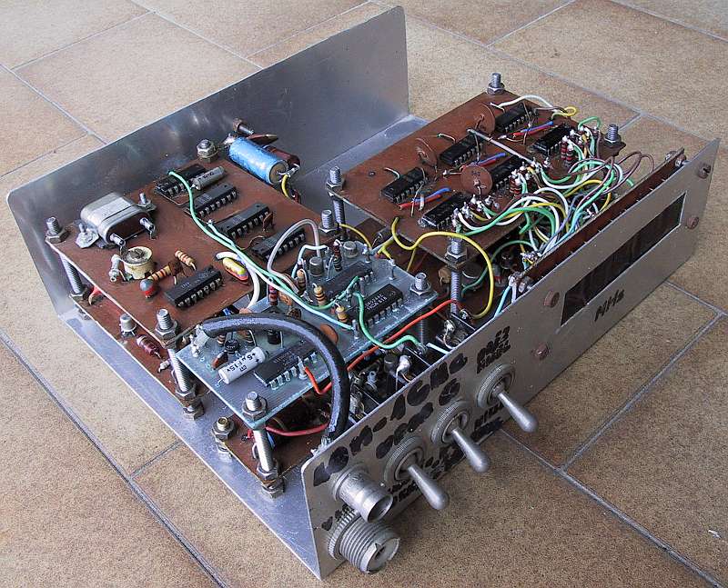
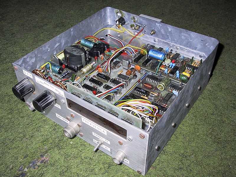
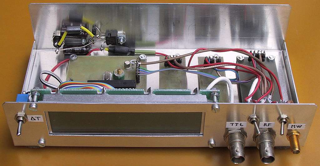
Therefore I decided to design a simple, easily-reproducible counter around a PIC 16F876A. The basic counter rate is extended to at least 180MHz using two 74Fxx devices. A divide-by-64 prescaler is used for higher frequencies up to at least 4.5GHz. All results of the measurement are shown on an inexpensive, 2x16 alphanumeric LCD module with large characters.
The counter has three inputs: a microwave (prescaled) input, an RF input and a TTL input. The microwave and RF inputs are AC coupled and terminated to a low impedance (around 50ohms). The TTL input is DC coupled and has a high input impedance. A progress-bar indicator is provided on the LCD for the gate timing.
Both the microwave and RF inputs have an additional feature, usually not found in frequency counters: a simple signal-level detector driving yet another bar indicator on the LCD module. This is very useful to check for the correct input-signal level as well as an indicator for circuit tuning or absorption-wave-meter dip display (Lecher wires).
References:
[1] Matjaz Vidmar: "A Microwave Analog Frequency Divider", pages 120-126/11-1998, Microwave Journal, International Edition, ISSN 0192-6225, Euro-Global Edition, ISSN 0192-6217.
[2] Zeljko Bozic, S52ZB: "13GHz Prescaler", pages 89-94/2-2006, VHF-Communications, ISSN 0177-7505.
* * * * *