(THEORY)
(DESIGN)
(ASSEMBLY)
(OPERATION)
(ATTENUATOR)
(HOME)
DDS RF Signal Generator
Matjaz Vidmar, S53MV
3. Assembly
The DDS RF signal generator includes four single-sided printed-circuit boards: two larger 60x60mm boards for the CPU and DDS modules, a smaller 30x30mm board for the keypad and another smaller 43x20mm board for the LCD voltage doubler, if required. All four printed-circuit boards are etched on an 1mm-thick FR4 laminate. The recommended copper thickness is 17.5um to avoid excessive underetching. The corresponding PCB files and full-scale drawings are downloadable at the end of this article. A reduced-resolution (150dpi) image is presented here:
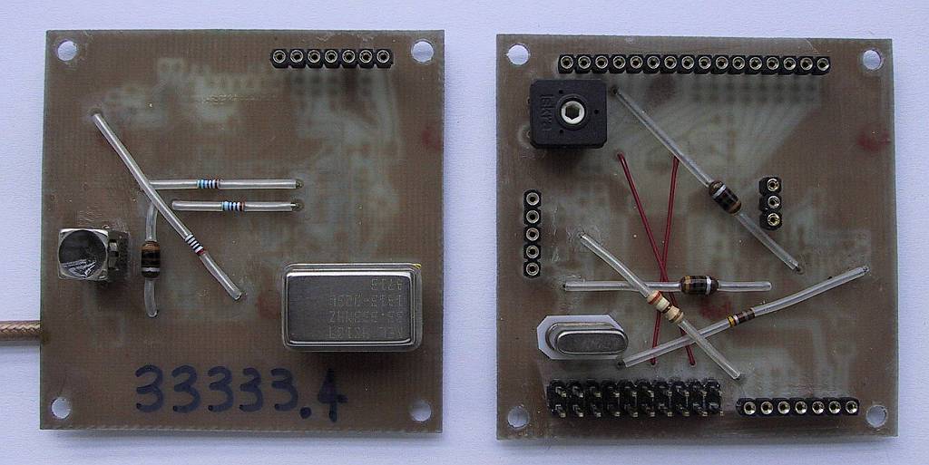
There are just a few conventional components installed on the top side of both larger boards. These include connectors, a crystal, a trimmer, an oscillator, a balun transformer and some resistors and inductors used as bridges:
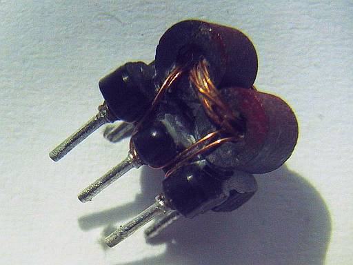
The balun transformer requires a careful selection of the magnetic core first. A simple selection rule is to use high-permeability ferrite beads and select those that provide the highest impedance in the frequency range of interest. The transformer includes 3+3 turns for the primary winding and 3 turns for the secondary winding. The finished transformer is installed on the base of a 7x7mm IF transformer as shown on the following picture:
Finally the whole transformer with its base is inserted in the original shielding can of the IF transformer and the latter is filled with glue. The prototypes exhibited a flat response from 200kHz to 200MHz. The finished transformer, RF-output cable and connector and keypad are shown on the following picture:
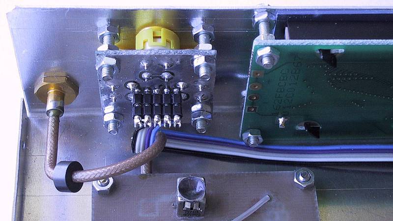
In order to improve shielding, a double-braid cable is recommended together with an appropriate female SMA connector on the front panel. The ferrite bead on the cable also helps shielding. The keypad includes just four normally-open pushbuttons and a connector.
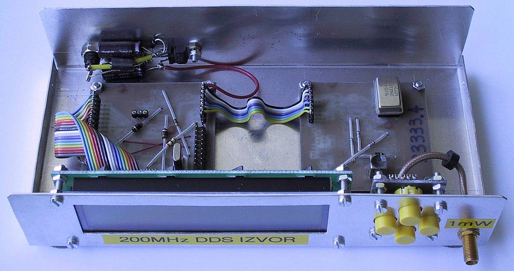
The generator is installed in a box made of aluminum sheet. The bottom is made from 1mm-thick aluminum sheet, the cover is made from 0.6mm-thick aluminum sheet and the LCD is protected by a small piece of plexiglass. The useful internal width is 200mm, depth 100mm and height 45mm.
The RF connector, keypad and LCD module are installed on the front panel:
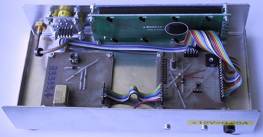
The power-supply connector is installed on the rear panel:
(THEORY) (DESIGN) (ASSEMBLY) (OPERATION) (ATTENUATOR) (HOME)