Fig.1 - Oscillator block diagram.
(VCO)
(SA)
(TG)
(HC)
(SN)
(MC)
(LCD)
(HOME)
Wide-band & Low-Noise Microwave VCO
Matjaz Vidmar, S53MV
1. Oscillators for spectrum analyzers
An important piece of radio-frequency or microwave test equipment is certainly the RF spectrum analyzer. Spectrum analyzers can roughly be divided in two groups: professional and low-cost. Although there are many differences between these two groups of instruments, the most important difference is in the type of (sweep) oscillator used for the first frequency conversion.
Professional spectrum analyzers use YIG (Yttrium-Iron Garnet) oscillators. YIG resonators can be tuned over wide frequency ranges (more than an octave in the microwave frequency range) with an external DC magnetic field. YIG resonators also have a high Q allowing a low phase noise when used in an oscillator. Finally, the tuning characteristic of a YIG oscillator is linear, since the frequency is directly proportional to the applied DC magnetic field.
Low-cost spectrum analyzers use varactor (varicap) tuned oscillators. The Q of varactor diodes is rather low and is inversely proportional to the operating frequency. Silicon varactors usually have the Q less than 30 at 1GHz. GaAs varactors are somewhat better, but they are not easily available and are much more expensive. The frequency coverage of low-cost spectrum analyzers is therefore limited below 1GHz and the phase-noise performance is usually 20-30dB worse than that of YIG oscillators.
A spectrum analyzer can also be built by a skilled radio amateur. While most circuits of professional spectrum analyzers can be reproduced in amateur conditions, the major problem is building a wide-band, low-noise VCO for the first (swept) conversion. YIG oscillators probably can not be built in amateur conditions. The price of a new commercially-available YIG oscillator is comparable to the price of a surplus professional spectrum analyzer.
A varactor-tuned VCO covering the frequency band 2-4GHz will be presented in this article. Such a VCO allows the design of a spectrum analyzer with the first IF in the 2GHz range, similar to professional instruments. The phase noise of the described VCO is reasonably low, within 20dB of a free-running YIG oscillator. Finally, the VCO design is fully reproducible using standard SMD parts installed on a conventional FR4 (0.8mm thick) printed-circuit board.
2. Some oscillator fundamentals
The design of an amateur RF spectrum analyzer therefore depends strictly on the type of VCO that is available for the first conversion. In order to explain the design of a wide-band varactor-tuned VCO, some oscillator basics have to be discussed first. Any oscillator must contain an active device (gain) and a feedback network, as shown on Fig.1. There are two conditions for oscillation: enough gain (including feedback loss) and correct phase of the feedback.
Fig.1 - Oscillator block diagram.
The frequency of oscillation is determined by both conditions as shown on Fig.2. However, close to the actual oscillation frequency, the gain curve has a broad and flat peak. Therefore, the exact frequency, the stability of the oscillator and the phase noise are all determined by the phase response. The steeper the phase slope, the better the stability of the oscillator and the lower the phase noise.
Fig.2 - Frequency of oscillation.
Low-frequency oscillators are usually designed for operation at a total phase shift of 2*PI radians. PI radians are usually provided by the active device (transistor) itself, while the remaining PI radians are provided by the feedback network. A steep phase slope is obtained by a high-Q LC tuned circuit or quartz-crystal resonator.
At frequencies above 1GHz the phase shift of all known active devices is much larger than PI radians due to chip and package parasitics. If an oscillator is designed for a total phase shift of 2*PI radians, then only a small fraction is left to the feedback network. The phase slope of the latter is certainly not very steep resulting in poor stability and high phase noise.
In the case of a variable-frequency oscillator, the frequency coverage is rather restricted since the influence of the feedback network is small compared to the active device itself. Conventional oscillator designs (with a LC circuit or transmission-line equivalent coupled to a negative-resistance active device will only provide a restricted frequency coverage and poor stability. Most microwave oscillators are designed in this way, since a negative resistance can easily be obtained from most microwave transistors when considering chip and package parasitics.
Replacing a negative-resistance device with a true two-port, unidirectional amplifier provides the oscillator designer with some more degrees of freedom. In particular, the feedback network can be tailored for the desired amplitude and phase response. The feedback network should both match the impedances and compensate the phase shift of the active device as well as introduce its own, frequency-dependent amplitude and phase response.
A successful wide-band microwave VCO design is shown on Fig.3, covering more than an octave with conventional silicon varactors. Although I developed this circuit for my first spectrum analyzer built in 1985, I published the circuit diagram one year later as part of a satellite-TV receiver indoor unit [1], [2]. Many other amateurs used this circuit in their own spectrum analyzers and other RF test equipment, but only few acknowledge the original source [3].
Fig.3 - Wide-band microwave VCO.
The major drawback of the VCO design from Fig.3 is that its operation is still based on lumped components: capacitors (varactors) and inductors. Its upper frequency limit is therefore defined by the parasitic inductance of available (packaged!) varactors to about 2-2.5GHz. The phase noise can be reduced by a carefully-designed bias regulator, to stabilize the current through the bipolar transistor, so that the impedances and phase shifts do not change.
3. Interdigital-filter microstrip oscillator
Active-device phase shifts become much larger at higher frequencies. For example, the phase shift inside a helium-neon laser tube may reach one million radians, although its theory of operation is the same as for other electrical oscillators. The total amplifier plus feedback phase shift still has to be an integer multiple "m" of 2*PI radians, however "m" is not restricted to unity and may become very large at light-wave frequencies.
Lumped-component oscillator designs become useless at microwave frequencies, since all available components behave as sections of transmission lines. On the other hand, additional phase shifts can be readily implemented as sections of transmission lines. The total phase shift of a microwave oscillator may be an integer multiple "m" of 2*PI radians. "m" may be larger than unity, but still relatively small at microwave frequencies.
Most microwave circuits are built in microstrip technology, since the latter is compatible with inexpensive manufacturing techniques like printed-circuit boards and surface-mount components. An example of a microstrip oscillator is shown on Fig.4. An interdigital band-pass filter is used as part of the feedback network. In order to bring the total phase shift to an integer multiple of 2*PI radians, additional delay lines may be required to obtain the correct feedback phase.
Fig.4 - Interdigital-filter oscillator.
Although the described oscillator may look complicated, it includes some advantages when compared to conventional low-frequency designs. Although the Q of microstrip resonators is not very high (in the range of 50-100), the phase slope may be made high thanks to the large total phase shift (increasing the multiple of 2*PI radians). On the other hand, oscillation at unwanted multiples of 2*PI radians can be suppressed by tailoring the amplitude response of the feedback network.
A fixed-frequency oscillator can be modified into a VCO by tuning the band-pass filter. For narrow-band operation it is sufficient to tune one of the quarter-wavelength fingers of the interdigital filter. A varactor is therefore inserted in the central finger, since the latter has the highest loaded Q and provides the highest tuning sensitivity.
The varactor should be inserted either in parallel with a voltage maximum or in series in a current maximum along the length of a resonator. Since the capacitance of most varactors is quite high for microwave frequencies, varactors are usually installed in series in current maxima. In the case of a quarter-wavelength resonator, the "cold end" of the latter is grounded through a varactor diode.
The circuit diagram of a narrow-band low-noise VCO is shown on Fig.5. The circuit diagram includes an output buffer (INA10386) to isolate the oscillator from load variations. Some supply voltage and tuning voltage filtering is included for the same purpose, as well as an output coupler for an auxilliary output.
Fig.5 - Narrowband low-noise VCO.
The tuning range of an interdigital oscillator with one single varactor is limited to about 10-20% of the central frequency. The frequency range of the oscillator on Fig.5 is about 1850-2200MHz. Outside this frequency range oscillation is not possible, since the gain maximum does not match the correct phase of the feedback.
A narrow-band low-noise VCO has many applications in frequency synthesizers. The phase noise is sufficient for both analog (SSB) communications [4], [5] as well as digital (coherent PSK) communications [8], [9], [10]. Used in a fast PLL it even allows the correct demodulation of complex radionavigation signals [6], [7].
The tuning range can be increased by increasing the coupling in the interdigital filter. This decreases the loaded Q of the resonators, degrading the phase-noise performance. Further, such an oscillator may also oscillate on higher-order resonances of the interdigital filter. This effect can be observed as "kinks" in the voltage/frequency curve, which is no longer monotonic.
4. Wideband low-noise microstrip VCO
To obtain a true wide-band microstrip VCO, all fingers of the interdigital filter have to be tuned. For example, inserting one BB833 varactor in each of the three fingers of the interdigital band-pass allows a tuning range up to 50% of the central frequency. For example, a VCO with three BB833 and a BFP183 (ft=8GHz) as the active device operates reliably in the frequency range 2.0-3.2GHz. Using a better transistor like the BFP420 (ft=25GHz) allows to shift the frequency range up to 2.6-3.8GHz.
A VCO with a contiguous frequency coverage of 1200MHz may look as the upper limit for BB833 varactors (minimum capacitance 0.75pF, series resistance 1.8ohm). Once again, even better results can only be obtained by changing our way of thinking. Varactors are usually considered as discrete lumped components while our oscillator is built with microwave transmission lines with distributed parameters.
In order to shift the frequency of a microstrip filter, one should preferably change the phase velocity on the microstrip transmission lines. The phase velocity of a microstrip line can be made variable if the line is periodically loaded with discrete variable reactances (varactors). Therefore, several varactors have to be distributed along the transmission lines to obtain the widest possible frequency coverage of a microstrip VCO. Since silicon varactors are inexpensive, 6 or even 9 diodes can be used in a single VCO circuit.
The circuit diagram of a wide-band, low-noise VCO is shown on Fig.6. Each microstrip resonator is tuned by two BB833 varactors, installed in different positions along the same resonator. This circuit configuration allows a very wide tuning range of about 2GHz around a center frequency of about 3GHz. In other words, the tuning range of the described varactor VCO matches the tuning range of YIG VCOs.
Fig.6 - Wide-band low-noise VCO.
On the other hand, a large number of varactors also increases the feedback losses. Further losses are introduced by the complicated varactor bias network (nine 22kohm resistors). All these losses must be recovered with the gain of the active device. A high ft transistor like the BFP420 is required for such an oscillator. Maybe the described oscillator could also be modified for other active devices, like GaAs FETs, HEMTs, HBTs o MMICs.
Just like its narrow-band counterpart the circuit on Fig.6 includes an output buffer (another BFP420 and an ATF35176 HEMT) to isolate the oscillator from load variations. The buffer frequency response is selected to partially compensate the output level variation across the octave frequency band. Some supply voltage and tuning voltage filtering is also included. An output coupler provides an auxiliary output, for example to feed a PLL prescaler, a frequency counter or a tracking generator for the spectrum analyzer.
The measured tuning characteristics of three wide-band VCOs are shown on Fig.7 and Fig.8. The main difference between VCO#1 and VCO#2 is in the printed-circuit board. VCO#2 uses lower impedance lines and the coupling between resonators is weaker. There are also differences in the BB833 varactors used: VCO#1 has rather old BB833s providing a coverage of only 1.8GHz while VCO#2 has new BB833s providing a coverage of 2GHz. Finally, VCO#3 is built on the same microstrip board as VCO#1, but uses the new BB857 varactors resulting in a frequency coverage of 2.2GHz.
Fig.7 - VCO tuning characteristics table.
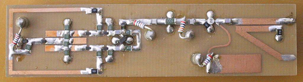
Fig.8 - VCO tuning characteristics diagram.
The tuning curves of all three VCOs are monotonic without kinks or jumps. The curves are quite non-linear as shown on Fig.8. All three curves are the steepest at band center around 3GHz (or at tuning voltages in the 5-10V range). Both below and above the tuning slope decreases, falling at the upper end (30V) down to less than 1/10 of the maximum slope. The frequency coverage of all three VCOs can be extended on the lower end by about 50MHz by applying a small negative voltage (about -0.7V) to the varactors.
The phase noise was accurately measured for VCO#1 and VCO#2 and the averaged results are shown on Fig.9. The phase noise is about 5dB worse at band center than at band edges. The phase noise peak coincides with the maximum tuning slope, indicating that at least part of this noise is caused by the varactors used and in particular by the 22kohm bias resistors.
Fig.9 - VCO phase noise.
In order to decrease the phase noise, the 22kohm bias resistors should be replaced by suitable RF chokes. Unfortunately suitable chokes are not easy to find. The resistor values can not be decreased much without introducing additional insertion loss in the feedback network. Finally, a more sophisticated bias regulator for the BFP420 oscillator transistor should also bring some improvement in the phase noise.
5. Practical microstrip VCO construction
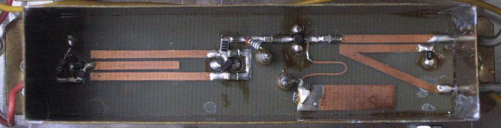
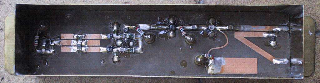
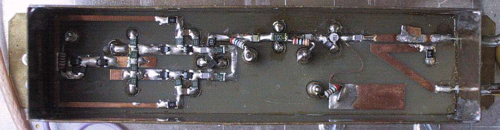
Both the narrow-band and the wide-band VCOs are built as microstrip circuits on conventional, double-sided, 0.8mm thick glassfiber-epoxy FR4 laminate. The upper sides are shown on Fig.10 while the bottom sides are not etched to act as groundplanes. Although the FR4 is quite lossy at microwave frequencies, the losses in the BB833 or BB857 varactors are even higher, so using inexpensive and easy-to-handle FR4 laminate is not a drawback.
Fig.10 - Printed-circuit boards (150dpi).
The dielectric constant and losses of 0.8mm thick FR4 laminate were found quite similar even for materials obtained from different suppliers. One should only be careful about the thickness, since the same microstrip VCO circuit may not oscillate at all on 0.7mm thick laminate (too weak coupling between microstrip lines) or cover a restricted frequency band on 0.9mm thick laminate (coupling too strong). An additional problem is the large temperature coefficient of the FR4 laminate, shifting the frequency of the VCO downwards with increasing temperature.
All three printed-circuit boards have the same dimensions: 20mm (width) X 80mm (length). The whole surface of the groundplane may be tinned, while one should try to avoid tin-plating the microstrip lines on the upper surface except for the areas where SMD components are installed. The boards do not have plated-through holes. All ground connections are made through 2.5mm diameter holes. The latter are first covered on the ground-plane side with thin (0.1mm) tinned copper foil and then filled with solder. The advantages of this grounding method are a low inductance to ground and easy removal of installed components, without damaging the board nor the component to be removed.
Supply and tuning voltages go trough several feed-through capacitors. Some feed-through capacitors (3 or 4) are installed in the printed-circuit board itself in 3.2mm diameter holes drilled at the marked positions. Wire-leaded 1/8W resistors are used to connect the feed-through capacitors to the microstrip circuit. Electrolytic capacitors, 220uH chokes and other filtering components are installed on the groundplane side and are supported directly by the feed-through capacitors.
Finally, two feed-through capacitors are also installed in the 0.5mm thick brass walls of the box housing the VCO. The box should be 30mm high, extending 20mm above the board surface and some 9mm below the board bottom. If the printed-circuit board is well soldered on all four sides to the brass frame, then no additional shielding is required on the bottom side with supply filtering components. On the upper side a shielding cover is required and some microwave absorber is recommended.
In the frequency range of interest only teflon-insulated coax cables should be used. Both flexible and semirigid teflon cables can be used. The cable end should be first prepared by tinning both the inner conductor and the shield. Then the inner conductor should reach the microstrip board through a 3.2mm diameter hole in the brass walls, while the shield is soldered all around the perimeter of the hole.
The microstrip boards should be checked before installation in the shielding enclosure. Both narrow-band and wide-band VCOs should be checked for frequency coverage and output power level. In particular the PCB#2 for the wide-band VCO may require some trimming of the central resonator length if the power drops or the oscillator stops at low tuning voltages. The output power of the buffer amplifier should not drop below +10dBm in any of the oscillators shown.
6. Applications of microwave varactor-tuned VCOs
Microwave VCOs have many applications. Narrow-band VCOs are suitable for many frequency-synthesizer projects. Wide-band VCOs are mainly intended for instrumentation, like CW and sweep generators, spectrum analyzers and corresponding tracking generators. In the following paragraph a simple spectrum analyzer using both described VCOs will be presented, although for space reasons the description will be limited to the block diagram as shown on Fig.11.
Fig.11 - Spectrum-analyzer block diagram.
The design of a spectrum analyzer is based mainly on the available wide-band VCO. Considering the frequency coverage of the described VCOs and the amateur microwave allocations (1.3GHz and 2.3GHz) and satellite frequency bands (GPS at 1.575GHz, weather satellites at 1.7GHz) it makes sense to select the first IF at 2.1GHz. This is far enough from 2.3GHz and allows a simple input low-pass filter for the band from 0 to 1750MHz.
On the other hand, the last IF is set down to 10MHz (10.7MHz) due to the design restrictions of LC and crystal filters and the logarithmic detector. To simplify image and spurious filtering, the first IF at 2.1GHz is first converted to a second IF of 70MHz and the latter is afterwards converted to the final third IF of 10MHz.
The IF filters offer six different bandwidths: 4MHz, 700kHz, 150kHz, 50kHz, 20kHz and 10kHz. The 4MHz bandwidth is required for full-band sweeps, considering the limited resolution of the CRT display. On the other side, the resolution of the spectrum analyzer is limited to 10kHz bandwidth and 50kHz/div display. Narrower IF filters would require additional stabilization circuits for all oscillators. Since narrow IF filters also require very slow scanning, they are practically seldom used and were omitted in this project.
The logarithmic detector is built with discrete components, since available integrated circuits will not handle a dynamic range of over 90dB (achieved already with the 150kHz IF filter) and many different IF bandwidths at the same time. The following video amplifier provides a 20dB/V output to drive the vertical deflection of the CRT display as well as an AF (earphone) output. Of course the latter is only useful at zero span.
On the other hand, the horizontal deflection signal (5Vpp) is provided by the built-in sawtooth oscillator. The latter may sweep the frequency of the first local oscillator (wide-band VCO) or the frequency of the second local oscillator (narrow-band VCO for 500kHz/div or less). Due to the nonlinear voltage/frequency response, the wide-band VCO requires a rather complex linearization circuit.
The spectrum analyzer is designed to use a standard XY oscilloscope display. If an external X deflection is not available, the spectrum-analyzer electronics also provides trigger pulses for the time base of the oscilloscope display. Z-axis or display blanking has two functions in a spectrum analyzer: retrace blanking and out-of-band blanking. If a Z-axis (intensity) input is not available on the CRT display, then the blanking output (open collector) may be wired in parallel with the Y output to deflect the trace outside of the visible screen when the blanking is active.
Original full-size drawings

References:
[1] Matjaz Vidmar: "Empfangsanlage fuer TV-Satelliten, Teil 2: Die Innenenheit", pages 194-215/4-86, UKW-Berichte/VHF-Communications.
[2] Matjaz Vidmar: "TV Satellite Receive System, Part 1: Low-Noise 11 GHz Down-Converter, Part 2: Indoor Unit", pages 1-19 & 20-40, UKW-Berichte/VHF-Communications, Reprint for Siemens AG, Munich, W.-Germany.
[3] Dr. Ing. Jochen Jirmann: "Breitband-VCO in Microstrip Technik", pages 3-11/1-92, UKW-Berichte/VHF-Communications.
[4] Matjaz Vidmar: "A Satellite Receiving Front-End for 2400MHz", pages 195-217/Scriptum der Vortraege, 39. Weinheimer UKW Tagung, 17-18 September 1994.
[5] Matjaz Vidmar: "Ein Front-End fuer den Satellitenempfang im 13-cm-Band", pages 21-33/2-94, AMSAT-DL Journal.
[6] Matjaz Vidmar: "Selbstbau eines Empfaengers fuer GPS- und GLONASS-Satelliten, Teil 4", pages 10-24/1-94, UKW-Berichte.
[7] Matjaz Vidmar: "A DIY Receiver for GPS and GLONASS Satellites, Part-4", pages 35-51/1-95, VHF-Communications.
[8] Matjaz Vidmar: "13cm PSK Transceiver for 1.2Mbits/s Packet Radio, Part-1", pages 130-147/3-96, VHF-Communications.
[9] Matjaz Vidmar: "13cm PSK Transceiver for 1.2Mbit/s Packet Radio", pages 145-175/15th ARRL and TAPR DIGITAL COMMUNICATIONS CONFERENCE, Seattle, Washington, September 20-22, 1996.
[10] Matjaz Vidmar: "Ein PSK-Transceiver fuer 2.4GHz am Beispiel eines 1.2Mbit/s Daten-Transceivers", pages 179-190/3-97, UKW-Berichte.
* * * * *