(ZIF SSB)
(1.3, 2.3 & 5.7GHz)
(10GHz)
(3.4GHz)
(24GHz)
(HOME)
ZERO-IF SSB/CW TRANSCEIVER FOR 24GHz
Matjaz Vidmar, S53MV
1. Electronic components at 24GHz
The zero-IF microwave SSB/CW transceivers, developed in the 1997-1999 time frame, covering all amateur-radio frequency bands between 1.3GHz and 10GHz, have been very successful. These transceivers have been reproduced successfully in hundreds of units by skilled amateur builders. A large part of this success is certainly due to the no-tune design of most RF circuits.
At frequencies below 3GHz, available transistors provide plenty of gain thus simplifying the design of a no-tune radio. In the frequency range between 5GHz and 15GHz, the packages of most GaAs FETs and HEMTs provide good impedance matching in a 50ohm system, making a no-tune design even simpler. The design of discrete-transistor amplifiers becomes difficult above 20GHz. While most popular HEMTs provide around 10dB of gain at 20GHz, this figure quickly drops to zero dB at 30GHz.
Although packaged (micro-x) GaAs FETs and HEMTs are able to provide useful gain between 20GHz and 30GHz, their particular behavior is very difficult to predict in this frequency band. New semiconductor packages may change this statement but unfortunately at the time of developing the 24GHz zero-IF SSB/CW transceiver (1999) these were not available yet. A no-tune design at 24GHz is therefore not possible using micro-x packaged devices.
Most experiments were done with the ATF35076 (ATF35176 or ATF35376) HEMT series, but very similar results were also obtained with the MGF4918D HEMTs coming from a different manufacturer. After careful tuning, these devices provide 6...7dB of power gain at 24GHz. At the same time, the same devices may provide more than 15dB of gain in the 10...15GHz frequency range.
Building a stable multistage amplifier for 24GHz is very difficult due to this very high gain in the 10-15GHz range. Some selectivity has to be built in a 24GHz amplifier just to prevent self oscillation at lower frequencies. Unfortunately, these selective elements further decrease the little available gain at 24GHz.
Long-term failure modes of microwave transistors are a further concern. Most microwave designers know the slow degradation problem of silicon transistors when used as multipliers or other class-"C" operation. HEMTs have a similar slow degradation (slow decrease of the Idss, just a few percent per week!) when operated in power stages at higher-than-usual supply voltages.
Fortunately this does not happen with conventional GaAs FETs. In any case, the dual class-"B" (zero quiescent voltage) with current and voltage limits as used in the zero-IF SSB/CW transceivers for 1.3GHz, 2.3GHz, 3.4GHz, 5.7GHz and 10GHz proved very reliable in practice, both using GaAs FETs and HEMTs. It was therefore obvious to try the same solution at 24GHz as well.
Suitable mixer diodes for 24GHz are easier to find. The 24GHz zero-IF transceiver was designed around the BAT14-W02 diodes packaged in the very small SCD80 SMD package. Unfortunately there are no packaged PIN diodes that could operate in an antenna RX/TX switch at 24GHz. An alternative solution was found for the 24GHz transceiver that does not require any PIN diodes nor unreliable mechanical switching components.
In order to keep circuit losses small, 19mils (0.5mm) thick teflon laminate has to be used at 24GHz. Although a 50-ohm microstrip on this laminate is still a single-mode waveguide at 24GHz, the same is no longer true for the harmonics generated by mixer diodes. It is therefore very important to keep the design of the mixers as much symmetric as practical to avoid the propagation of higher-order modes along the microstrip lines. Although the harmonic power is rather small, harmonics are still strong enough to spoil the balancing of the mixers.
SMA connectors have to be selected carefully for operation at 24GHz. Angled connectors have parasitic resonances around 24GHz, therefore only straight connectors should be used. To minimize reflections at microstrip-to-coax transitions, the transition is first done to the thinner UT-085 semirigid cable and the coax diameter is afterwards expanded inside suitable SMA connectors.
While designs below about 4GHz can avoid resonances and other parasitic effects of the metal enclosures of microstrip printed-circuit boards, microwave absorbers and other special techniques are required above about 5GHz. As the metal enclosure becomes large compared to the wavelength, these problems become more difficult to manage as well. At the lower frequencies it is usually enough to damp single resonances of the metal box.
At 24GHz, the metal packages containing microstrip printed-circuit boards become so large that traveling waves provide spurious coupling in wide frequency ranges. In practice the circuit has to be split in many boards, shielded in individual boxes Most of the volume of the latter has to be filled with microwave absorber foam. Some microwave absorber may be required even outside the boxes due to shielding imperfections.
Considering all of the above, a zero-IF SSB/CW transciever for 24GHz is a much more complicated project than its predecessors for lower frequencies. Therefore the description in this article is intentionally made shorter, since the project is only intended for really experienced builders.
2. Modified VCXO and multiplier stages
Narrowband operation on 24GHz is currently centered around 24192MHz. A practical way to reach this frequency is to start from a third-overtone crystal at 28MHz or 42MHz. Such an oscillator usually has a much better stability and lower phase noise than popular designs with fifth-overtone crystals around 100MHz. Further, the frequency-pulling range of a third-overtone crystal matches the frequency-coverage requirements for narrowband SSB/CW operation at 24GHz.
Starting from a 28MHz crystal, it makes sense to triple to 84MHz, triple to 252MHz, double to 504MHz, double to 1008MHz, triple to 3024MHz and at the end multiply by four to 12096MHz. The final frequency doubling to 24192MHz is performed inside the subharmonic mixers in the transmitter and/or receiver.
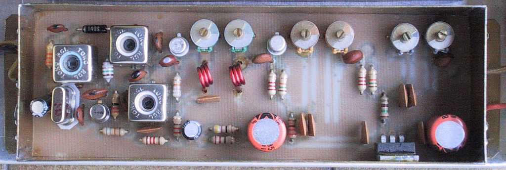
The frequency multiplications up to 1008MHz can be performed in a similar VCXO module as in other zero-IF SSB/CW transceivers. The same single-sided printed-circuit board is used with better semiconductor devices that allow reaching 1008MHz as shown on Fig.1.
Fig.1 - VCXO and multipliers for 1008MHz.
The following multiplication to 12096MHz requires an additional module built in microstrip technology on a 19mils (0.5mm) thick teflon board (120mmX20mm). This module includes four stages: a frequency tripler to 3024MHz, an amplifier at this frequency, a multiplier by four to 12096MHz and a final output amplifier to drive the subharmonic mixers as shown on Fig.2.
Fig.2 - Additional multiplier for 12096MHz.
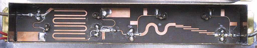
All stages use ATF35376 HEMTs as active and/or nonlinear elements. The additional multiplier module does not require any tuning to achieve more than 10mW of power at 12096MHz.
3. Quadrature transmit mixer for 24192MHz
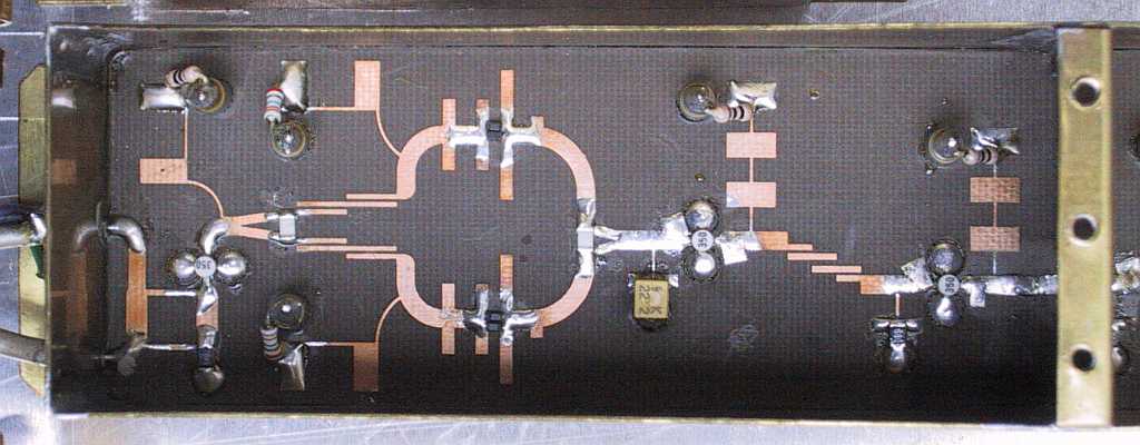
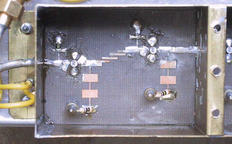
The SSB signal generation at 24GHz is performed in a quadrature mixer as in other zero-IF SSB transceivers. The design of the 24GHz quadrature mixer is based on the BAT14-02W (single) diodes and is described in detail in [1]. The quadrature transmit mixer includes a LO buffer, two subharmonic mixers in quadrature and two amplifier stages as shown on Fig.3 on a 19mils (0.5mm) thick teflon board (80mmX30mm).
Fig.3 - Quadrature transmit mixer for 24192MHz.
Since the output signal from the quadrature mixer module is rather weak (around -2dBm), an additional 24GHz transmit amplifier follows to boost the signal level to about +12dBm. The additional amplifier is shown on Fig.4 and is built on a 19mils (0.5mm) thick teflon printed-circuit board (39.5mmX30mm). All amplifier stages use ATF35076 HEMTs since the latter usually have a higher Idss and therefore higher gain than ATF35176 or ATF35376 selections of the same device type.
Fig.4 - Transmit amplifier for 24192MHz.
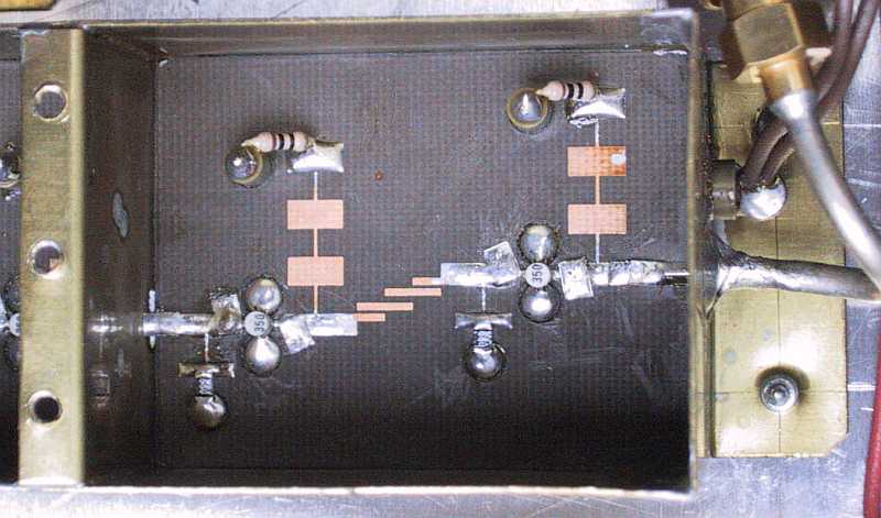
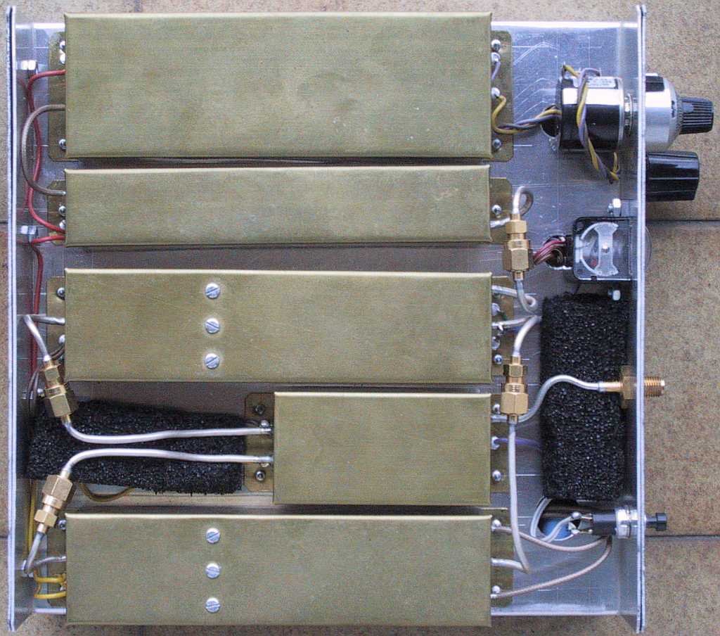
Both the transmit mixer and additional amplifier are installed in a 120mm long brass box, divided in two sections with a shielding wall. Microwave absorber foam is required in each section for proper operation.
4. RF front-end for 24192MHz
Since there are no suitable PIN diodes available for operation in the 24GHz band, a different solution had to be invented. If there are two identical transistors operating in quadrature in the transmitter output stage, the same transmitter transistors can be used for RX/TX antenna switching as described in detail in [2].
During reception, both TX transistors are biased to behave as fully reflective loads. The received signal is reflected back to the output quadrature hybrid. Considering the phases of the reflections, both signals sum on the receiver input port. The only drawback of this method is that any imbalance of the quadrature hybrid feeds part of the transmitter output directly into the receiver input.
The transmitter output stage includes two ATF35076 HEMTs in quadrature as shown on Fig.5. These transistors provide about +19dBm (80mW) of power at 24GHz. The same transistor type is used in the receiver input stage and can handle up to +10dBm of incident power. This should be more than enough considering the expected imbalance of the quadrature hybrids.
Fig.5 - RF front-end for 24192MHz.
The receiving section includes a three-stage low-noise preamplifier. Further receiver RF amplifier stages are located in the receiver mixer module. The RF front-end is built on a single 10mils (0.25mm) thick teflon printed-circuit board (60mmX30mm). The ground plane of the board is soldered to a 0.3mm thick brass plate for mechanical support. Both are installed in a single shielded box requiring lots of microwave-absorber foam.
5. Quadrature receive mixer for 24192MHz
The receiver is using the same type subharmonic mixers as the transmitter, equipped with BAT14-02W diodes. Since the noise figure of these mixers is rather high, another four RF amplifier stages are required in addition to the three stage LNA in the RF front-end. Two receive amplifier stages are included in the amplifier shown on Fig.6,
built on 19mils thick teflon board (39.5mmX30mm).
Fig.6 - Receive amplifier for 24192MHz.
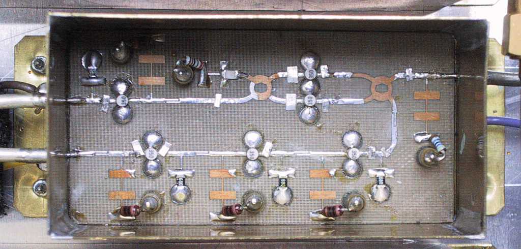
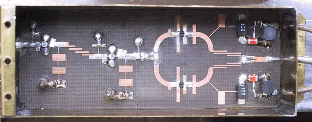
The final two RF amplifier stages, the quadrature mixer and the two IF preamplifiers are shown on Fig.7. These stages are assembled on a 19mils (0.5mm) thick teflon printed-circuit board (80mmX30mm). Both the amplifier and mixer are installed in a 120mm long brass box, divided in two sections with a shielding wall. Microwave absorber foam is required in each section for proper operation.
Fig.7 - Quadrature receive mixer for 24192MHz.
6. Construction of the zero-IF SSB transceiver for 24192MHz
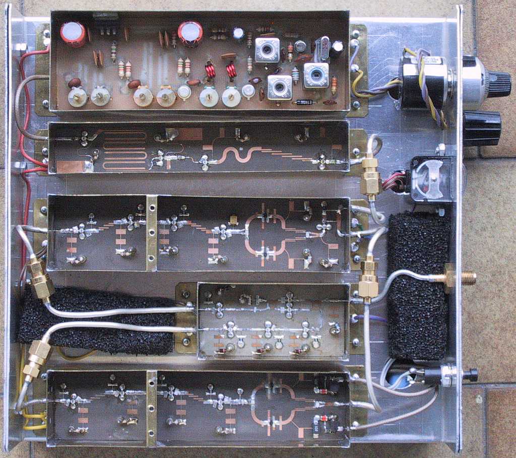
The zero-IF SSB/CW transceiver includes six microstrip teflon printed-circuit boards as shown on Fig.8. A more detailed file can be downloaded by pressing the archive icon. Five boards are etched on double-sided 19mils (0.5mm) thick laminate while the RF front end is etched on double-sided 10mils (0.25mm) thick laminate. Of course just one side is etched, the other is left unetched to act as a microstrip groundplane.
Fig.8 - Microstrip printed-circuit boards for the 24192MHz RTX.

Interstage DC decoupling at 24GHz is made either with coupled microstrips or with small capacitors made from 0.13mm thick, double-sided teflon laminate. All 24GHz amplifier stages require careful tuning by soldering small pieces of thin (0.1mm) tinned copper foil to act as open tuning stubs. The positions of these tuning stubs are well visible on the photos of the individual modules.
The 24GHz modules are connected with UT-085 semirigid cable. It is recommended that all 12GHz and 24GHz cables include one SMA connector pair for testing. Please note that cleaning the ready-made boards with alcohol will probably require new tuning, since even small amounts of flux around the tuning stubs changes their capacitance significantly. Large amounts of flux should be cleaned away before tuning since flux is a rather lossy dielectric at 24GHz.
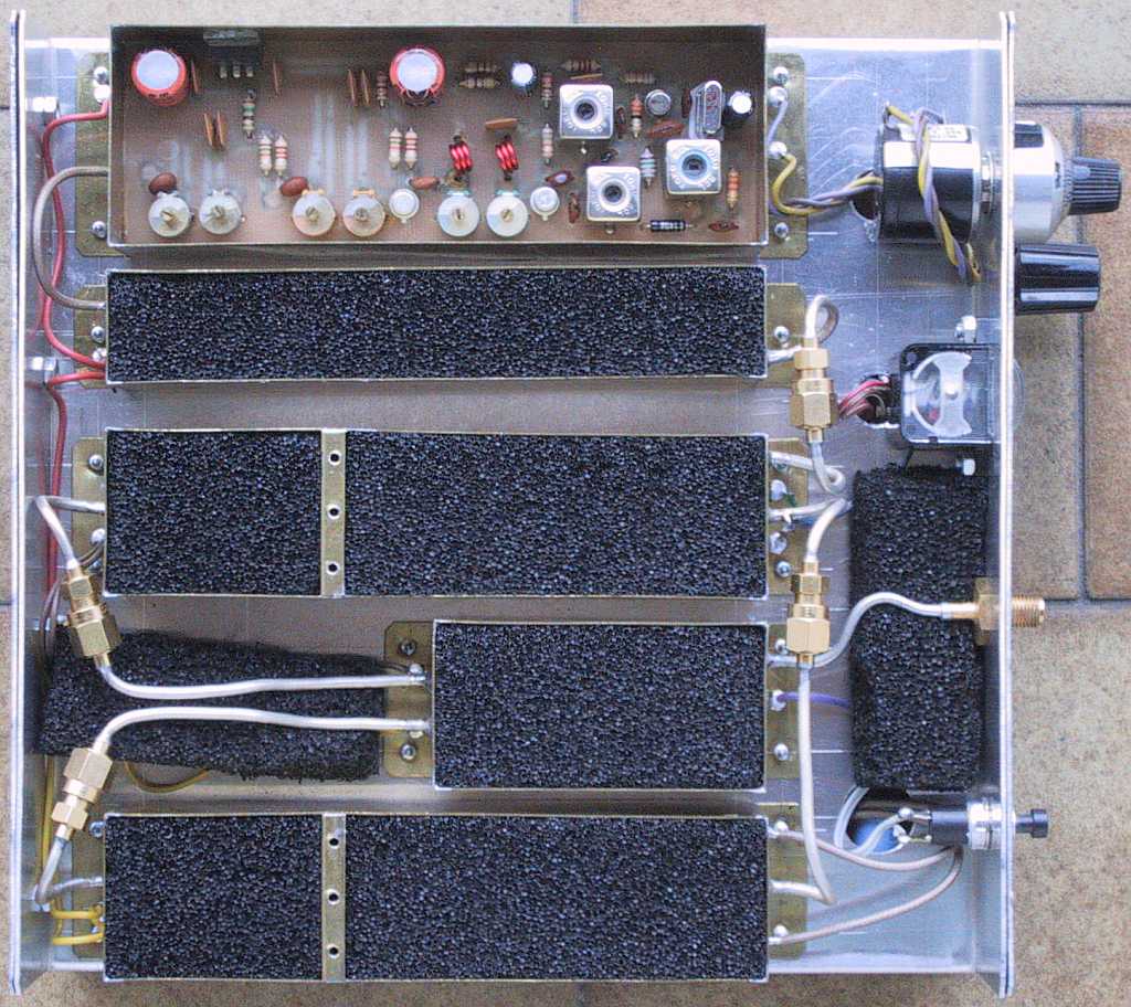
All microstrip modules require microwave absorber foam. Further, some pieces of microwave absorber foam are also required in the space among some modules due to the imperfect shielding of the module covers. To improve the latter, the covers of the receive and transmit mixer are attached with three small (2.2X6.5) sheet-metal screws to the intermediate shielding wall.
The IF and AF sections of the 24GHz SSB/CW transceiver are similar to the lower-frequency transceivers. Since there are no PIN diodes, no special PIN driver is required. The circuit diagram of the RX/TX supply switch is shown on Fig.9.
Fig.9 - SSB/CW switching RX/TX for 24192MHz.
Due to the several power-hungry amplifier stages at 24GHz, the overall current drain is around 600mA while receiving and 700...750mA while transmitting.
7. References
| [1] | Matjaz Vidmar: "K-band Quadrature Mixers with Plastic-packaged Diodes", pages 22-40/1-2000, Microwave Journal, International Edition, ISSN 0192-6225, Euro-Global Edition, ISSN 0192-6217. | 
|
| [2] | Matjaz Vidmar: "Use Transmitting Power FETs For Antenna Switching", pages 81-86/7-2000, Microwaves & RF, ISSN 0745-2993. |
|
* * * * *