(HISTORY)
(COUNTER)
(FRONTENDS)
(PROBES)
(ASSEMBLY)
(OPERATION)
(HOME)
Simple RF/Microwave Frequency Counter
Matjaz Vidmar, S53MV
6. Operation
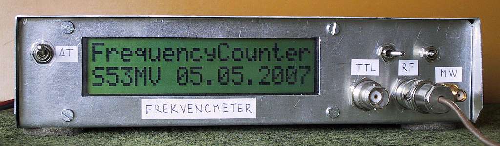
Immediately after power-up, the counter displays the software version/date for about one second.
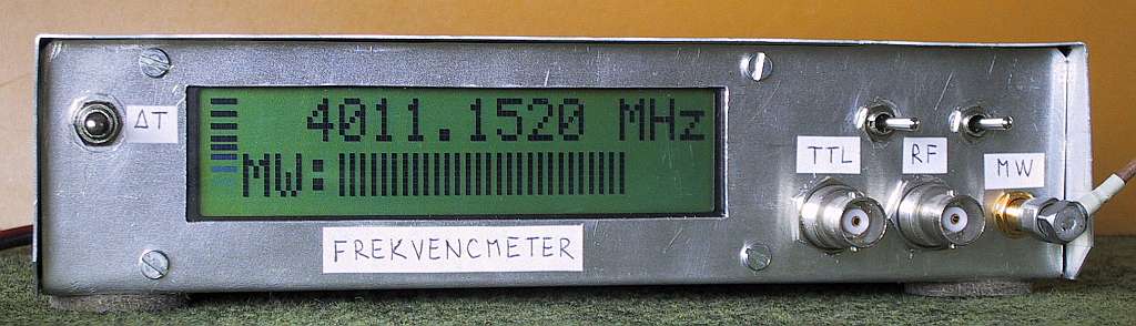
During normal operation, the leftmost characters of both rows are used as a vertical-bar display of the gate progress with 10 horizontal segments. The remaining 15 characters in the top row display the measured frequency. Three characters in the bottom row show the operating mode ("MW:", "RF:" or "TTL") and the remainig 12 characters are used as a horizontal-bar display of the signal strength with 36 vertical segments.
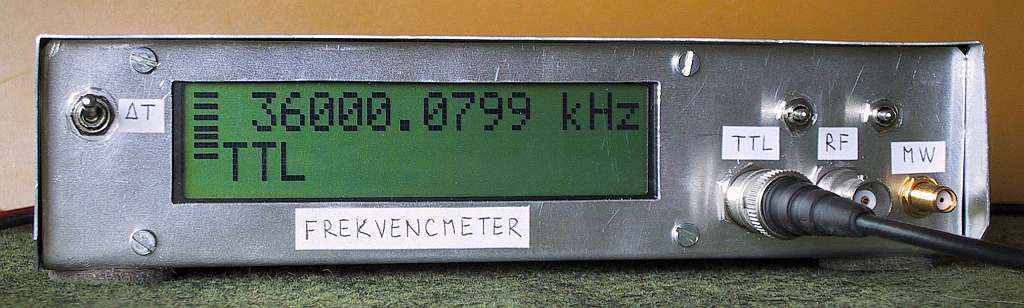
In the microwave mode both prototypes operated reliably up to 4.9GHz with an input-signal level of 0dBm (self-oscillating uPB1505 without 33kohm resistor). Below 3GHz the sensitivity improves to -30dBm. The 33kohm unbalancing resistor to stop self oscillations degrades this sensitivity by more than 10dB! Below 500MHz the sensitivity degrades again: the counter may count odd harmonics with too-low signal levels. The minimum usable frequency was found around 12MHz. The following picture shows the counter in the microwave mode with a gate time of 640ms corresponding to a resolution of 100Hz.
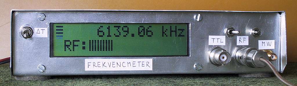
In the RF mode the 74F50109 allows counting up to about 220MHz. Reliable operation is possible up to 190-200MHz, depending on the internal wiring to the switches, with an input-signal level of 0dBm. The sensitivity improves from -20dBm at 180MHz down to -50dBm at 10MHz. The RF signal-level meter follows a similar increase in its sensitivity. This increase at lower frequencies matches the performance of the described loop probes! The following picture shows the counter in the RF mode with a gate time of 100ms corresponding to a resolution of 10Hz.
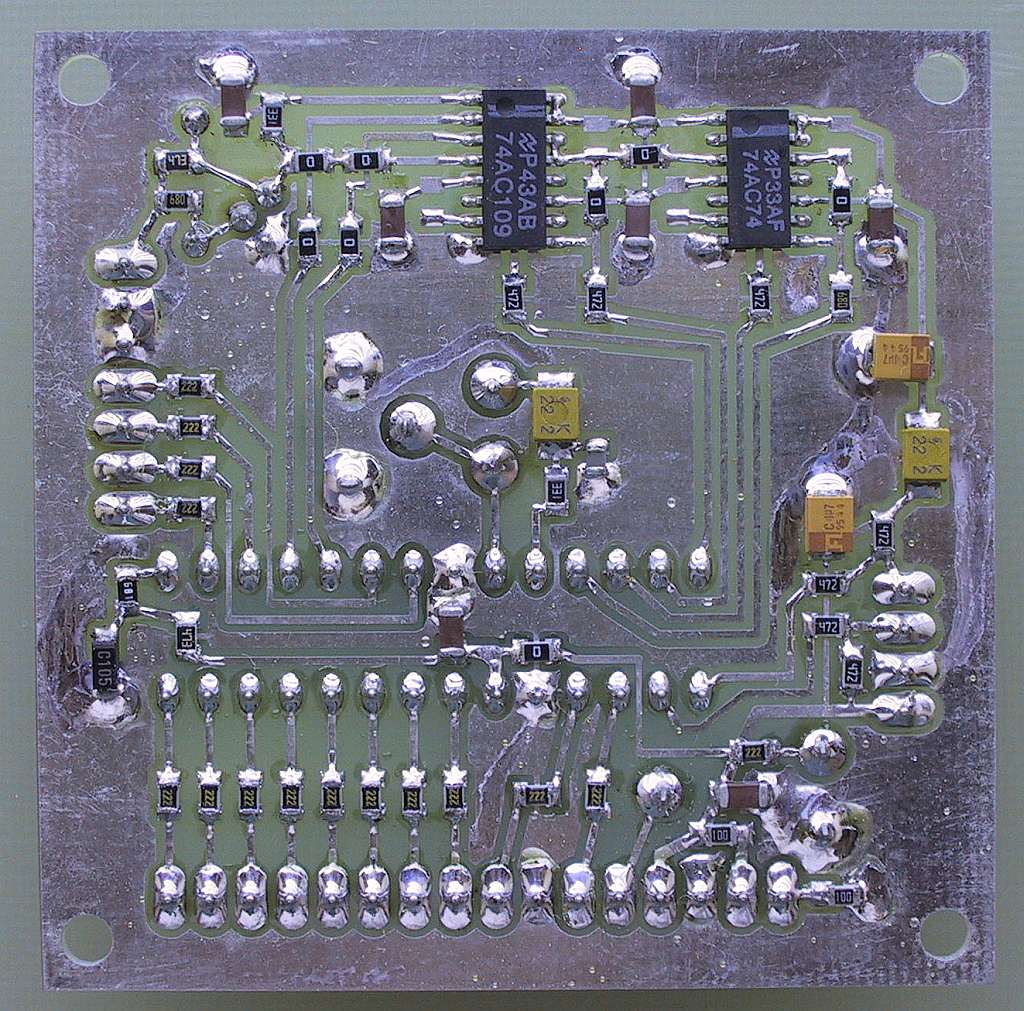
Unfortunately, the 74F50109, manufactured by Signetics (Philips) is not easily available. A 74F109 from the same manufacturer only operated up to about 140MHz. A combination of 74AC109 and 74AC74 (both from National Semiconductor) counted up to about 170MHz. The 74ACxxx logic circuits require a different input DC bias: replace the 2.2kohm resistor between the input and the collector of the 2N3960 with a 47kohm resistor. All four pull-up resistors can be omitted with 74ACxxx logic. Finally, the 2N3960 itself does not have many valid replacements. A 2N2369 will decrease the 74F50109 counting rate down to just 165MHz while RF and microwave transistors provide even worse results!
A much better choice is the 74LVC109. Although this device is specified for 3.3V operation, the maximum Vdd rating is 6.5V according to the 74LVC109 data sheet. Therefore it can replace the 74F50109 directly omitting the pull-up resistors. Since the 74LVC109 is a CMOS device, the 2.2kohm bias resistor between the input and the collector of the 2N3960 has to be replaced with a 33kohm resistor. The 74LVC109 allows the RF input of the counter to operate beyond 500MHz using a 74AC74 in the second stage! Above 500MHz counting may become unreliable due to limitiations of both the 74AC74 and the PIC 16F876A, the latter being guaranteed only to about 270MHz on the input. Further, in the 0.1Hz resolution mode, the 32-bit variables in the current software only allow counting to 429MHz.
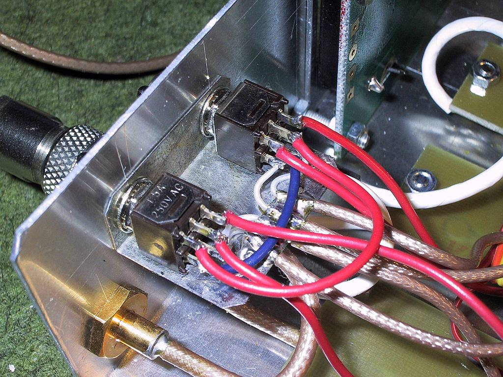
Finally, for operation above 200MHz a careful internal wiring among the different modules is required. Efficient grounding of the shields of all coaxial cables is particularly important. It is suggested that a small piece of L-shaped, pre-tinned metal sheet is installed under both switches having all cable braids grounded to it as shown on the following picture.
In the TTL mode the prototypes operated reliably beyond 100MHz. This frequency limit is however reduced by the coaxial cable feeding TTL signals and even more when using oscilloscope probes. The input-signal level is not indicated in the TTL mode. The built-in hysteresis allows reliable counting of very low frequencies, like the 50Hz mains. The following picture shows the counter in the TTL mode with a gate time of 10s corresponding to a resolution of 0.1Hz.
The current software version does not detect the mode switching before the end of the gate period. Therefore one may have to wait up to 10 seconds for the gate period to expire and another 10 seconds to get some meaningful reading. The current software also does not make any use of the measured signal level. Therefore it will display the self-oscillating frequency of the prescaler with no signal input in the microwave mode or any other invalid data due to low signal levels in the RF or microwave modes.
The software is designed using the same rules as the whole counter: keep this project useful, simple and straightforward. A simple prescaler is therefore used in place of a considerably more complex direct microwave counter. Some simple 74Fxxx logic ensures enough overlap between the prescaled microwave frequency range and the direct RF frequency range. A TTL input with hysteresis is an efficient solution for low frequencies and extreme duty cycles. Finally, an input-signal level indicator is an inexpensive but very useful addition to a frequency counter.
Last but not least, all detailed information like PCB files or software source code are made available in the following ZIP archive:
Full-scale drawings, PDF datasheets, PCB files & PIC software

* * * * *