1. BPSK RTX update
Several decades of AX.25 packet-radio networking left a comprehensive hardware heritage in Slovenia including mountain-top sites, antennas, cable installations, cabinets, power supplies and radio transceivers of all kinds. Much of this hardware is still useful today while deploying the new NBP network. Of course, new, even more efficient radio transceivers are also planned for NBP while old hardware requires maintenance and/or updates.
All megabit BPSK transceivers developed for the AX.25 SuperVozelj project are still useful today with NBP. Besides replacing electrolytic capacitors after many years of continuous operation, a complete list of maintenance, modifications and updates is available in the following article:
Old BPSK RTX update (SLO)

The content of the above article will be briefly summarized here. Old BPSK transceivers (1995) for 2360MHz with double conversion receivers (75MHz/10MHz) can only be used at 1.2288Mbps with some limitations. All ZIF-BPSK transceivers can be modified for operation at 2Mbps or more.
In all ZIF receivers it makes sense to check the quadrature (symmetry and phase shift) of the ZIF chain. A CW signal generator has to be connected to the receiver input. A frequency offset of about 100kHz is recommended so that the I and Q signals can be compared with an oscilloscope at different locations in the ZIF chain.
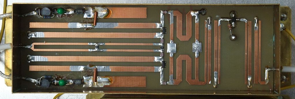
Small differences (1..2dB) between the I and Q outputs of the receiving mixer can be corrected by soldering small pieces of copper foil on the quadrature hybrid. The 1.27GHz ZIF-BPSK RTX usually requires such trimming on the transverse arms of the quadrature hybrid:
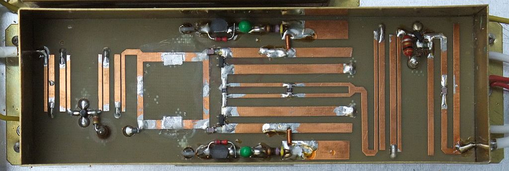
On the other hand, the 2.36GHz ZIF-BPSK RTX may require such trimming on the longitudinal arms of the quadrature hybrid:
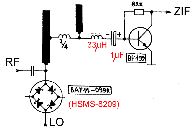
The schottky quads BAT14-099R are no longer available, but may be replaced by the HSMS-8209 schottky quads. For best performance, the original choke (differing values in different versions) and the original 4.7uF tantalum electrolytic capacitor have to be replaced with a 33uH choke followed by a 1uF capacitor:
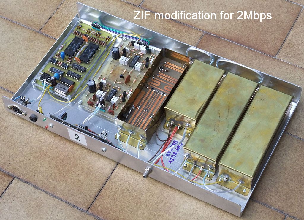
The old dual-channel ZIF (1996) with many BF199 transistors and corresponding demodulator with two 74HC4067 analog switches require several modifications for operation at 2Mbps, including the removal of one complete ZIF stage:
Even with all of the modifications in place, the BF199 ZIF loses some 2-3dB S/N ratio when compared to new NE592-ZIF chains. A much better solution is to remove the two old BF199-ZIF and 74HC4067-demodulator modules and replace them with the latest SMD ZIF chain (2011) described here later as part of the "Low-power ZIF-BPSK":
The improved BPSK demodulator (2001) with 8 comparators LM311, 74HCxxx logic and NE592 ZIF already works as it is at 2Mbps. For best performance at 2Mbps, a few modifications to the NE592-ZIF chain are recommended:
The same circuit diagram of the improved BPSK demodulator is also used in the latest SMD version (2011), except that the 74HCxxx logic in the Costas loop is programmed into a CPLD (Altera EPM3032ATC44).
2. ZIF-BPSK RTX for 430MHz
The block diagram of a ZIF-BPSK transceiver may look quite simple:
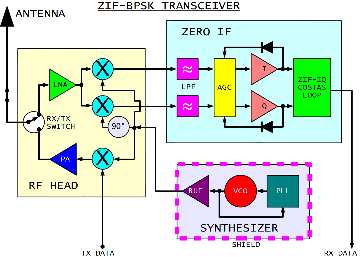
In the real world there is a hidden problem. Some radio frequency may leak from the antenna back into the frequency synthesizer. Such a leak causes unwanted frequency modulation of the VCO. The resulting carrier instability may corrupt so much the BPSK signal to make it useless.
In the BPSK transceivers developed for the SuperVozelj network, the above problem was avoided by not using frequency synthesizers at all. All of the required frequencies were obtained by crystal oscillators followed by complex multiplier chains.
In the meantime, professionals found a workaround called fractional PLL. A fractional PLL does not produce such a clean spectrum as a conventional, integer PLL. On the other hand, the comparison frequency of a fractional PLL can be made several orders of magnitude faster to actively suppress any external unwanted modulation of the VCO. Fractional PLLs are widely used in WLAN (WiFi) equipment, since they allow the integration of a complete radio transceiver on a single chip.
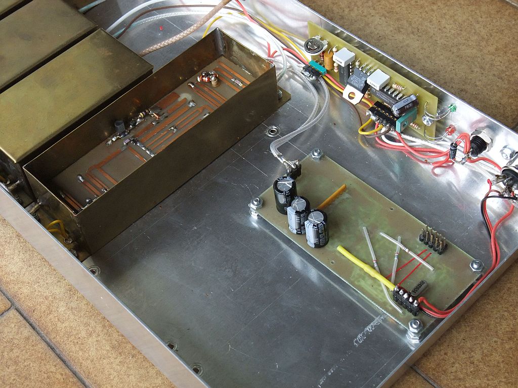
If reasonably good shielding is available, a conventional, integer PLL could also be used in a BPSK transceiver. The first attempt was to build a prototype BPSK transceiver for 430MHz, since less absolute frequency instability is expected at lower frequencies. The whole frequency synthesizer was installed in a brass box while the ZIF used recycled modules form 1.27GHz and/or 2.36GHz transceivers:
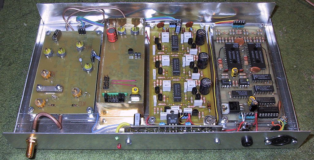
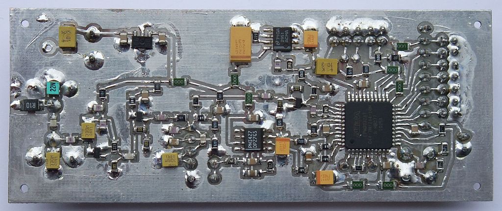
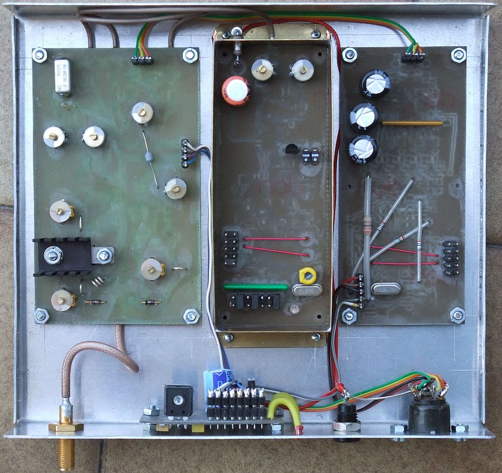
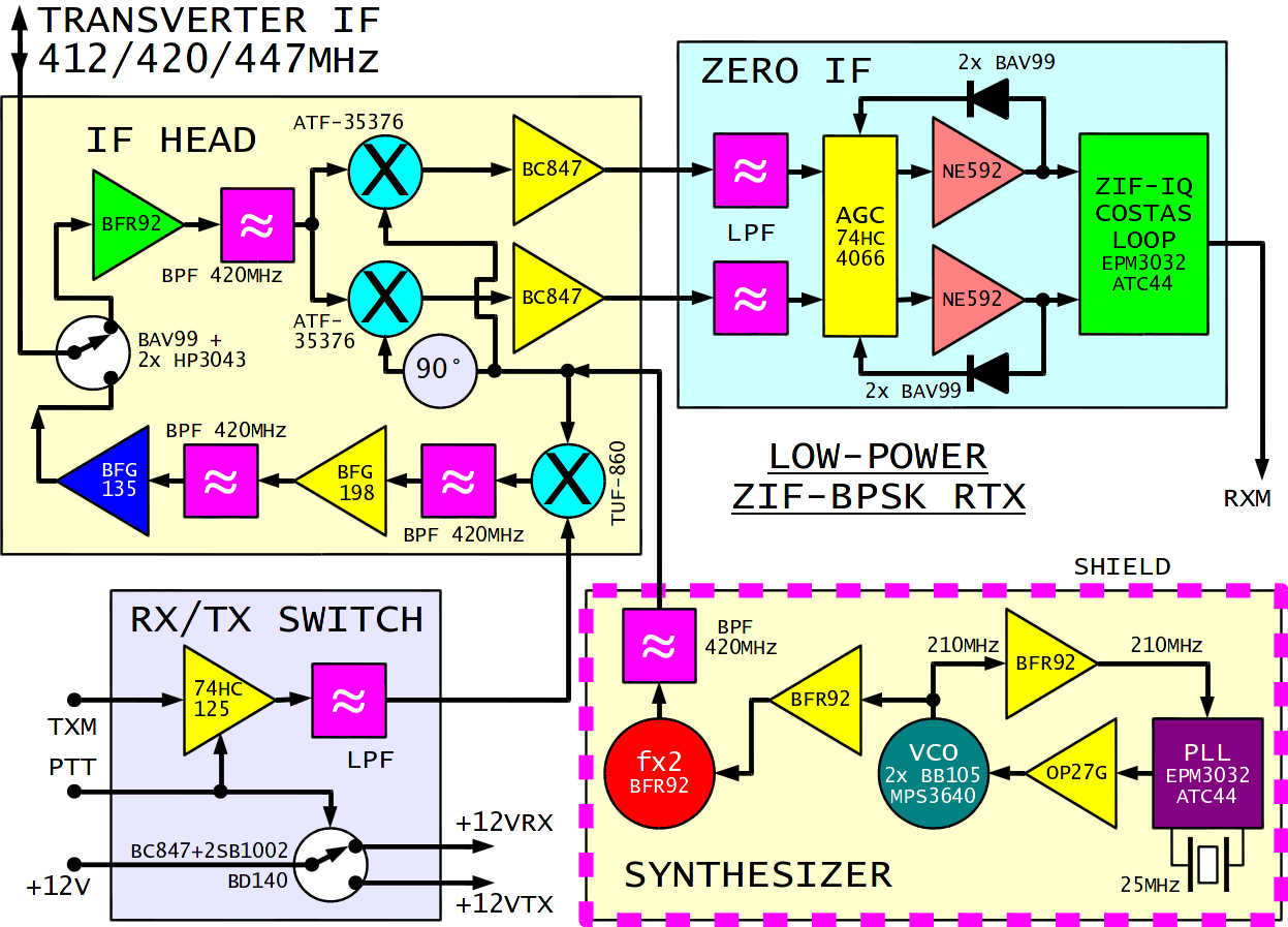
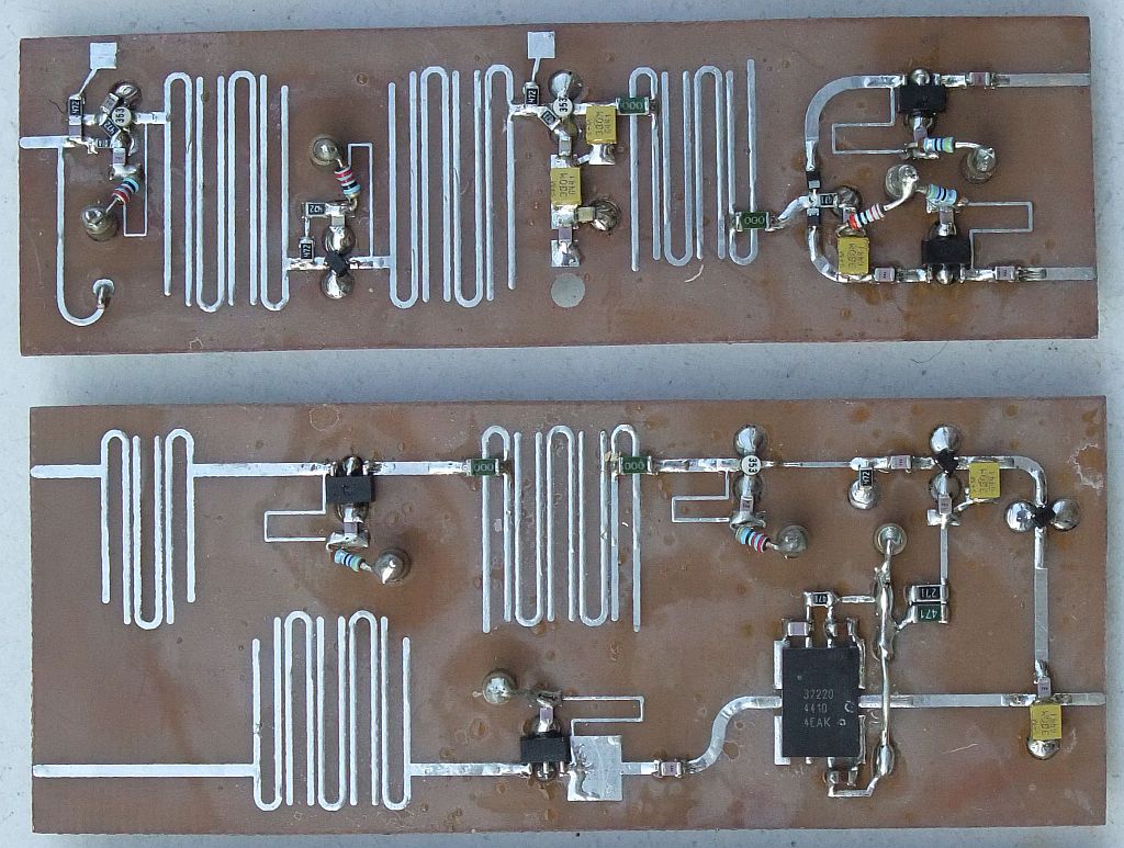
Since the prototype results were encouraging, a new ZIF built with SMD components and CPLD logic was developed. The whole 70cm BPSK transceiver only includes three RF printed-circuit boards and is not much more complicated nor much larger than the simple 70cm WBFM RTX developed two decades ago:
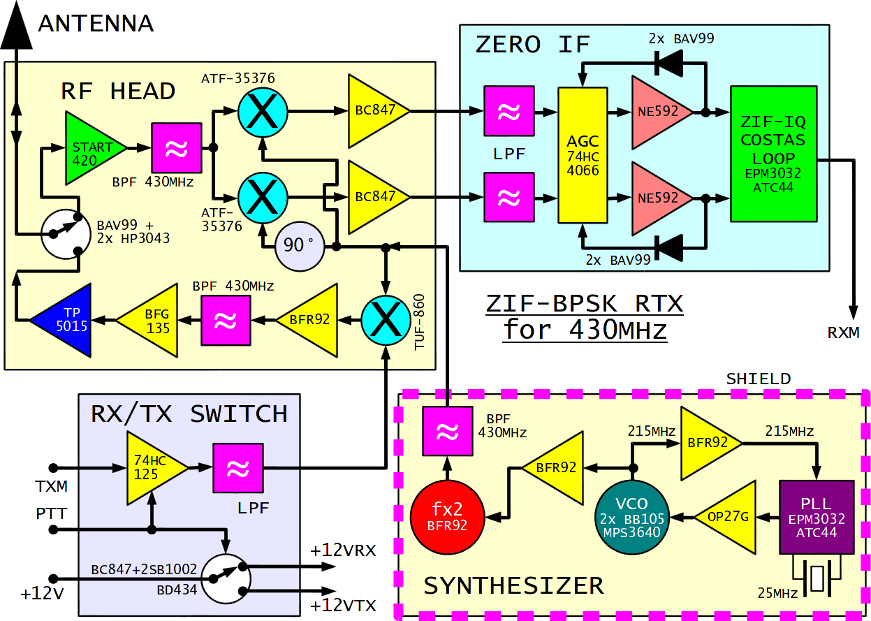
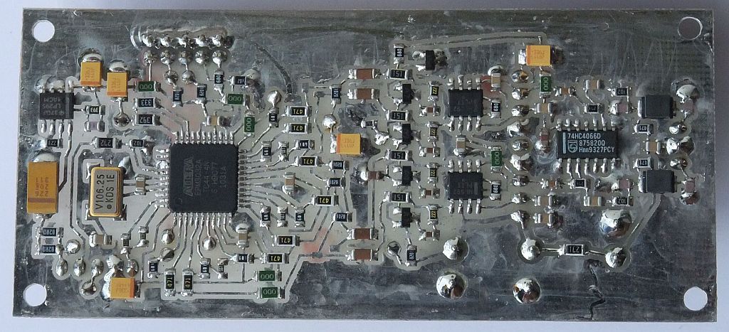
The synthesizer VCO operates at half of the final frequency to further reduce shielding requirements. The PLL logic is programmed into an Altera EPM3032ATC44. The latter is fully static by design and avoids using unreliable microcontrollers in the frequency synthesizer.
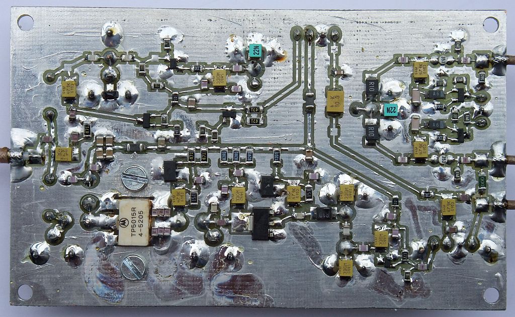
The RF head includes HEMT mixers in the receiving chain and a doubly-balanced diode mixer as the BPSK modulator in the transmit chain. The power amplifier is designed with a large safety margin including a 24V/15W transistor TP5015 in the output stage. The antenna switch uses two PIN diodes HP3043 and the receiver input is further protected by a BAV99 limiter:
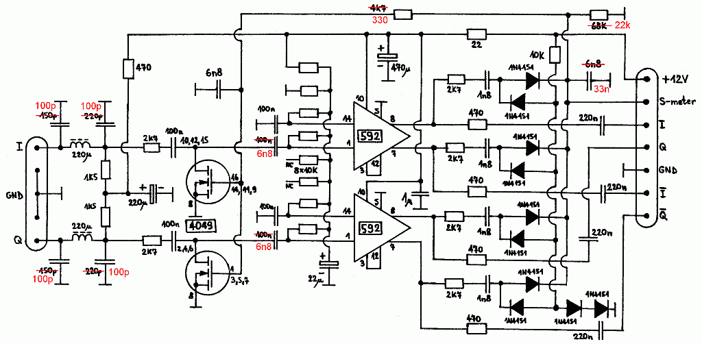
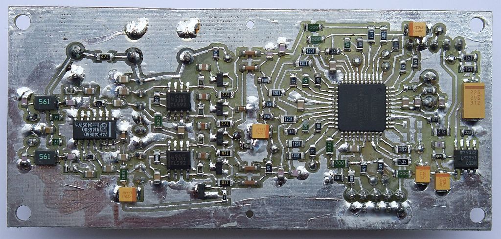
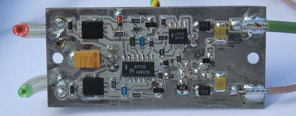
The ZIF chain includes an AGC stage (74HC4066), two NE592 amplifiers (SOIC-8 version) and a Costas-loop demodulator programmed into an Altera EPM3032ATC44 CPLD. The inputs of the latter are biased into linear operation to accept analog signals directly without additional comparators. The Costas loop uses a DPLL/1024 in the version for 1.2288Mbps, 430MHz:
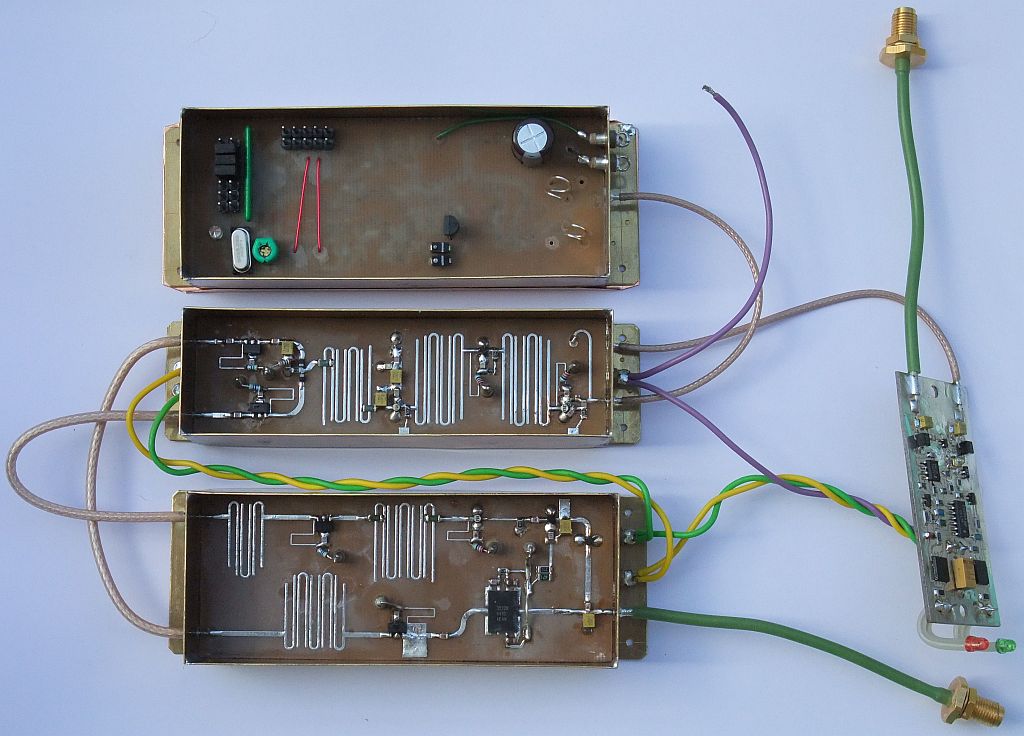
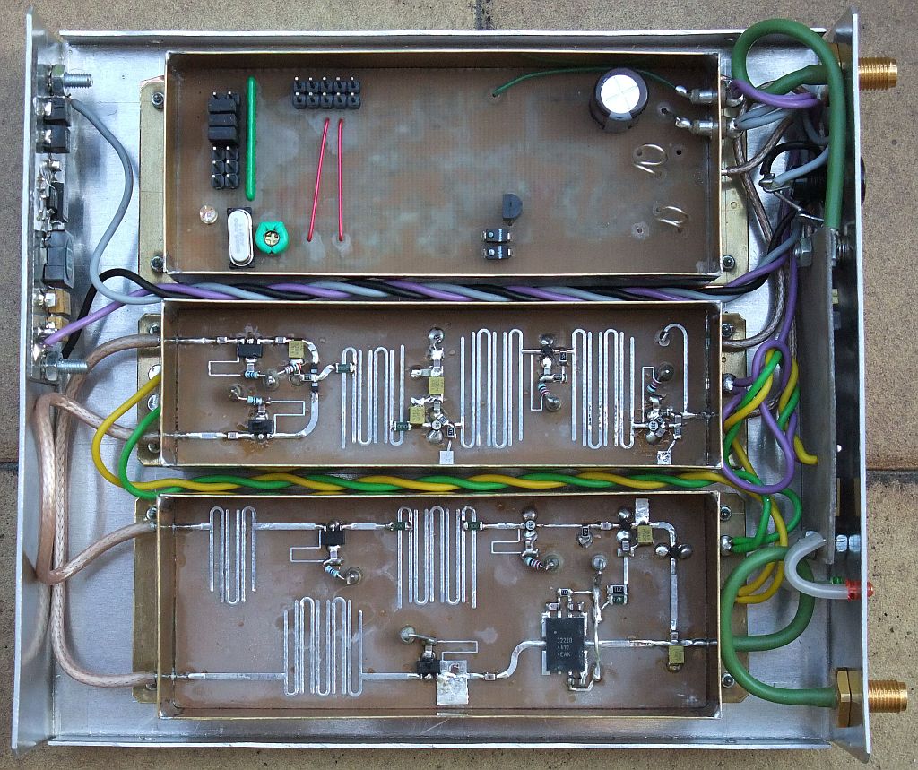
The whole ZIF-BPSK transceiver for 430MHz is 170mm wide, 150mm deep and 30mm high:
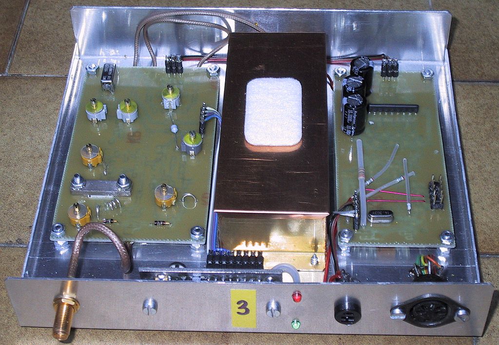
Only the frequency synthesizer requires additional shielding:
A much more detailed description of the ZIF-BPSK RTX for 430MHz including all circuit diagrams is available in the following PDF document. The corresponding design files including printed-circuit boards and firmware for both CPLDs are included in the following ZIP archive:
ZIF-BPSK RTX for 430MHz description (SLO)
ZIF-BPSK RTX for 430MHz files
Using 1.2288Mbps BPSK in the 430MHz band might cause interference to other users. Some simple calculations show that the likelihood of interference to narrow-band users is very small provided that the operating frequency and antenna polarization of the BPSK link is chosen carefully:
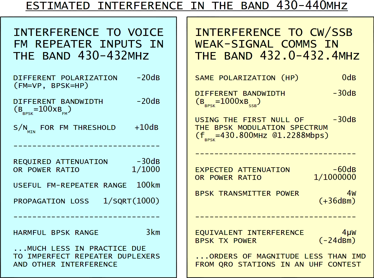
In practice, no complaints about interference from 1.2288Mbps BPSK transmissions were ever received although some BPSK links in the 430MHz band were intensively used every day for a period of two years. On the other hand, the BPSK links occasionally suffer interference from narrow-band users.
The ZIF-BPSK transceiver for 430MHz excels in non-line-of-sight links:
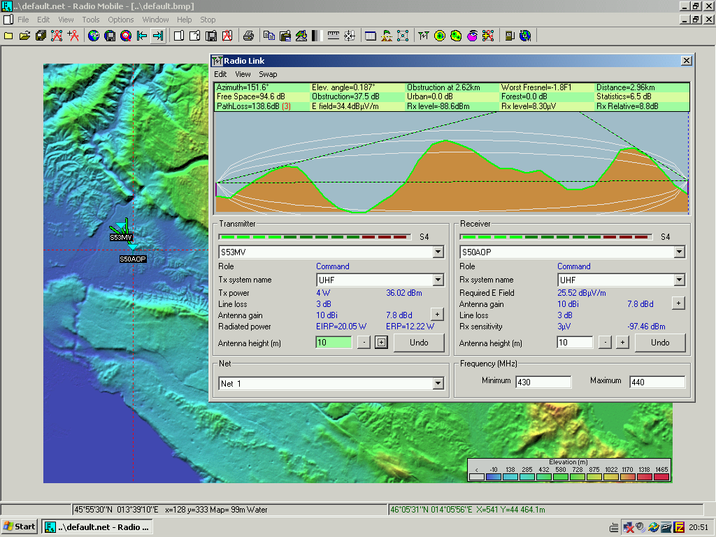
In the above example, a pair of ZIF-BPSK transceivers for 430MHz transfers as much as 80kbytes/s using TCP/IP over NBP with a 10dB power margin. No known professional equipment (2012) can match this result in such unfavorable conditions and no commercial WLAN (WiFi) equipment can ever come close!
3. Low-power ZIF-BPSK RTX
A packet-radio network also requires mountain-top network nodes. Frequently, radio-amateur equipment is only a guest in some larger telecommunication or broadcast installation. In these conditions, amateur equipment has to accept long antenna cables, interference from high-power professional transmitters, severe size limitations of both amateur antennas and equipment cabinets and last but not least restricted access to the site, especially to the antenna tower.
The problem of a long antenna cable can be handled in different ways:
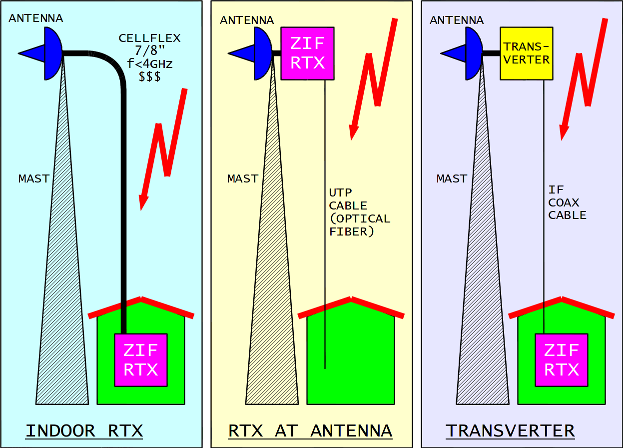
Thre traditional solution is to have all electronics indoor and use expensive antenna cables like Cellflex 7/8". This solution is not scalable, since the larger the coax cable, the lower its cutoff frequency caused by higher-order waveguide modes.
The inexpensive commercial WLAN (WiFi) solution is to put all electronics close to the antenna. Inexpensive data cables, UTP or optical fiber, are used to connect to the indoor equipment. Copper data cables like UTP or STP are not really designed to operate in a difficult electromagnetic environment, like high-power broadcast transmitters or nearby lightning strikes. Electronic equipment maintenance on the antenna mast is difficult if possible at all.
An intermediate solution is to put part of the electronics, the microwave head, close to the antenna and the remaining electronics, IF modulators and demodulators, indoor. Losses in the IF coax cable can be overcome easily and the same cable can be used for power supply to the antenna unit. Although this solution is the most complex, professional microwave links use it regularly.
Considering amateur packet-radio links of a few megabits in the 2.3GHz and 3.4GHz frequency ranges, an intermediate frequency around 400MHz is a reasonable choice. Such a "transverter" microwave link offers yet another possibility for amateur-radio experiments. Besides connecting two or more *ATNCs to a single IF unit, two or more IF units can be connected to the same outdoor RF head using a simple, passive IF coupler:
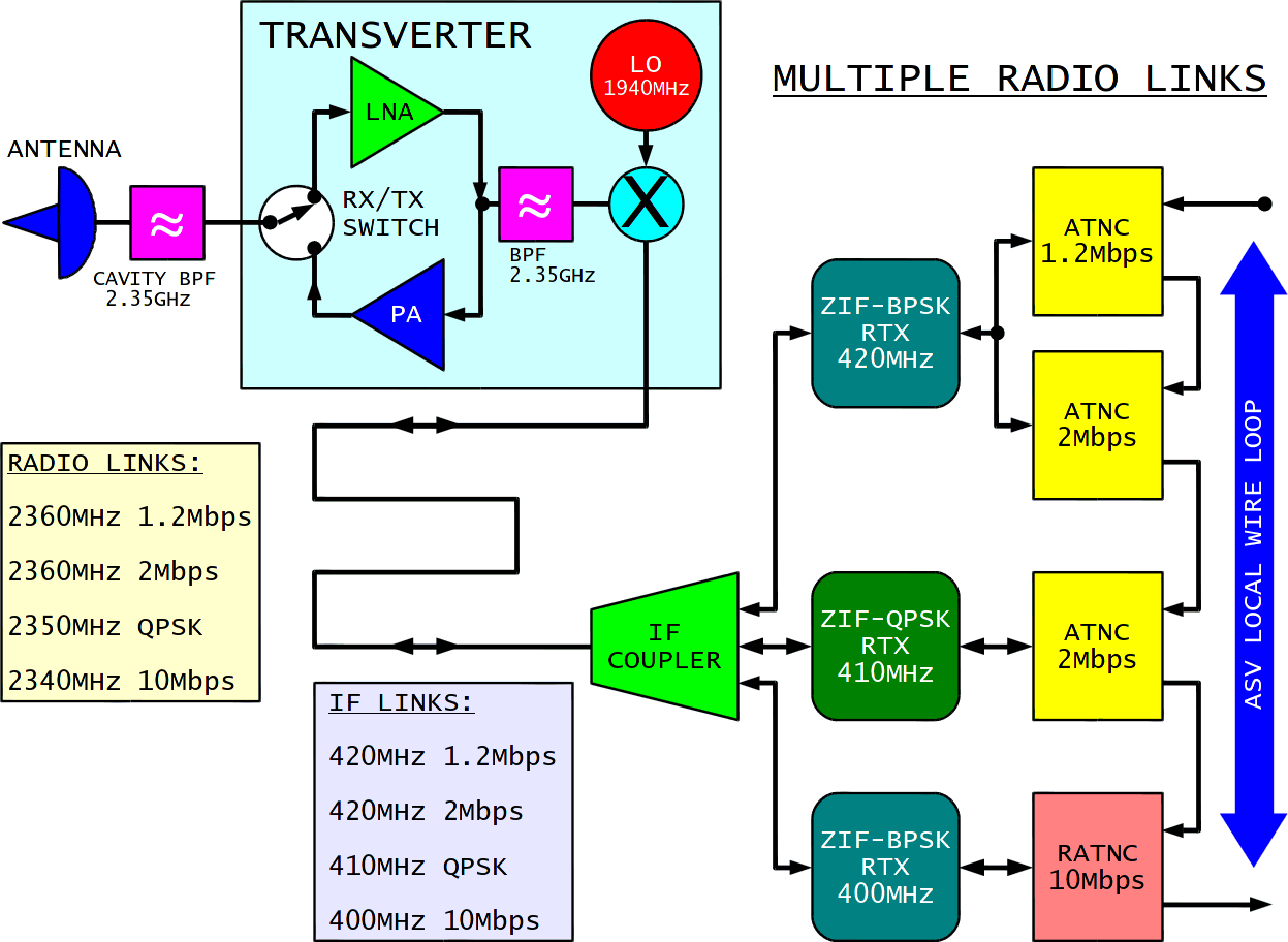
Of course, only a single IF unit is allowed to transmit at the same time. A cavity filter is required at the antenna to limit interference in the unfortunate case of two or more simultaneous transmissions. Additional IF units allow experimenting with different modulation formats and very different data rates. A common antenna and a common RF head allow a fair comparison among different modulation techniques in our experiments. Most important of all, adding new experimental equipment does not require any work on the antenna tower!
The ZIF-BPSK RTX for 430MHz could be tuned to be used as an IF in the 400MHz band. A better solution is to redesign this transceiver for a lower transmit power, a lower receiver gain, faster RX/TX switching, higher data rates and tolerating wider carrier-frequency errors as expected when using microwave transverters:
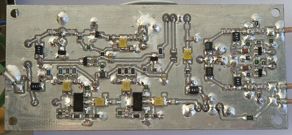
The RF head is redesigned and now becomes an IF head. The main differences are in the transmitter power amplifier. The output power of the new design is reduced to 200mW and both amplifier stages operate in class "A" with a strong feedback for stability:
The modifications to the other modules only include a few component values for higher data rates and different firmware to be programmed in the two CPLDs. The PLL CPLD is programmed for a lower frequency range. The Costas-loop CPLD is programmed for a DPLL/256 to tolerate wider carrier-frequency errors as expected in the microwave frequency bands.
The low-power ZIF-BPSK RTX is 150mm wide, 150mm deep and 30mm high, therefore slightly narrower than the full-power version for 430MHz:
Another successful experiment was to replace the unreliable and expensive capacitive trimmers in the RF/IF tuned circuits with fixed SMD capacitors. The corresponding SMD coils had to be replaced with air-wound, silver-plated copper wire coils. Circuit tuning was accomplished by coil stretching:
A much more detailed description of the low-power ZIF-BPSK RTX including all circuit diagrams is available in the following PDF document. The corresponding design files including printed-circuit boards and firmware for both CPLDs are included in the following ZIP archive:
Low-power ZIF-BPSK description (SLO)
Low-power ZIF-BPSK filesThe PLL and ZIF printed-circuit boards include a few minor corrections and may also be used in the full-power ZIF-BPSK RTX for 430MHz with some advantages. The same PLL printed-circuit board is also used in the corresponding BPSK transverters for 2360MHz and 3405MHz. Several different version of the low-power ZIF-BPSK RTX have been built for 412MHz, 420MHz and 447MHz for both 2Mbps and 10Mbps BPSK. The 10Mbps version includes several small modifications (low-pass filter, bias components) and a new ZIF printed-circuit board:
The crystal is replaced with an 106.25MHz oscillator in the DPLL/1024. The much higher clock increases the current drain of the EPM3032ATC44 CPLD to over 100mA. This high current drain caused overheating of the built-in LP2951 linear regulator. To avoid failures, the latter was finally replaced with a LM1117 regulator in all 10Mbps radios including the ZIF-BPSK RTX for 1245MHz.
4. BPSK transverter for 2360MHz
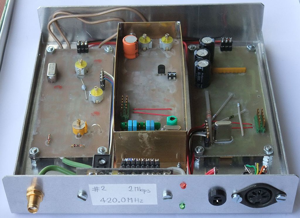
A BPSK transverter for 2360MHz had to be developed first to replace old BPSK transceivers (1995) for 2360MHz with double conversion receivers (75MHz/10MHz). The latter could only be used at 1.2288Mbps with some limitations, like rather slow RX/TX switching. Of course, the new transverter should include a wide bandwidth and fast RX/TX switching to allow present and future packet-radio network extensions:
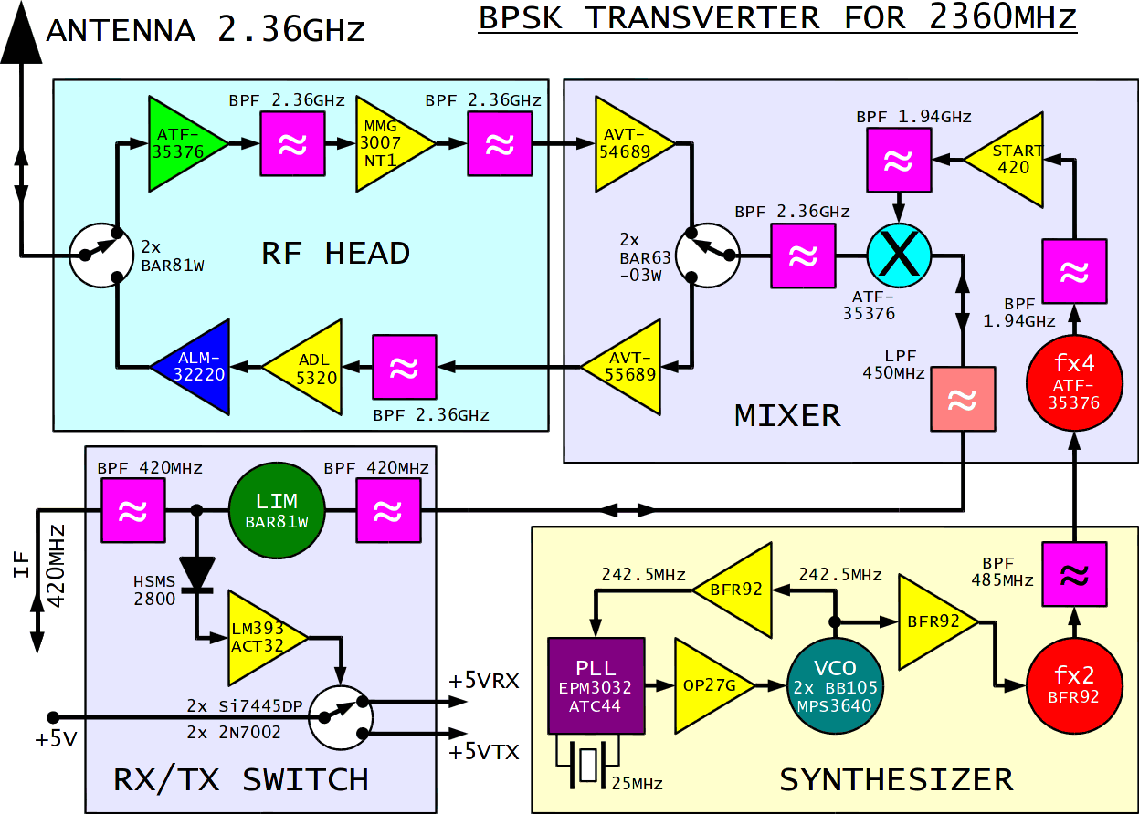
The transverter uses a single, passive HEMT mixer for both transmission and reception. The receive and transmit amplifier chains at 2.36GHz are switched by PIN diodes. MMIC amplifiers allow a simple design of low-power stages at the expense of higher power drain. The transmitter uses an ALM-32220 hybrid amplifier to achieve 2W of RF power at the antenna connector, including losses in the antenna switch.
The RF head an mixer are built on two microstrip printed-circuit boards etched on 0.6mm-thick FR4 laminate. The latter introduces losses especially in the bandpass filters that have to be compensated by the MMIC amplifiers. On the other hand, a lossy laminate helps to avoid unwanted millimeter-wave oscillations of HEMTs. Microstrip bandpass filters with unsymmetrical frequency response are used as appropriate:
The IF limiter (AGC) allows IF-drive power levels between 20mW (+13dBm) and 200mW (+23dBm). The same IF-drive signal also controls the RX/TX switching of the transverter. Fast and reliable, IF-driven RX/TX switching requires quite some electronic components:
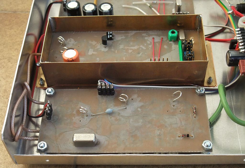
Both microstrip modules and the frequency synthesizer are installed in three brass frames for shielding:
The whole 13cm transverter is 135mm wide, 150mm deep and 30mm high including a switching power regulator for +5V:
The shape of the printed-circuit boards is selected to avoid unwanted resonances in the frequency range below 4GHz. The brass frames therefore only require covers from thin copper sheet while microwave absorber foam is not required:
A much more detailed description of the BPSK transverter for 2360MHz including all circuit diagrams is available in the following PDF document. The corresponding design files including printed-circuit boards and firmware for the CPLD are included in the following ZIP archive:
BPSK transverter for 2360MHz description (SLO)
BPSK transverter for 2360MHz filesPractical experiments show that the receiving section of the described BPSK transverter offers similar sensitivity and interference rejection as the old BPSK and ZIF-BPSK receiver designs. The transmitting section of the described BPSK transverter provides some 6-7dB improvement in the link margin thanks to the higher output power (around 2W) when compared to the old BPSK transmitters with the CLY2 output stage generating 400-500mW. The transverter spurious emissions are 40-50dB below the desired signal at 2360MHz and can be totally eliminated with an external cavity filter.
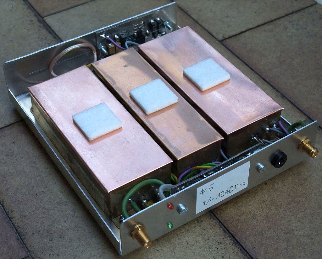
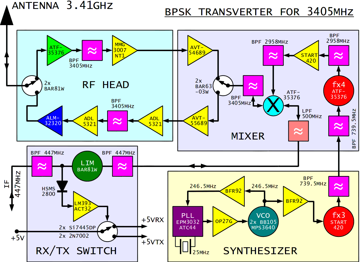
5. BPSK transverter for 3405MHz
A BPSK transverter for 3405MHz is quite similar to its 2360MHz counterpart:
The transverter uses a single, passive HEMT mixer for both transmission and reception. The receive and transmit amplifier chains at 3.41GHz are switched by PIN diodes. MMIC amplifiers allow a simple design of low-power stages at the expense of higher power drain. The transmitter uses an ALM-32320 hybrid amplifier to achieve 2.5W of RF power at the antenna connector, including losses in the antenna switch.
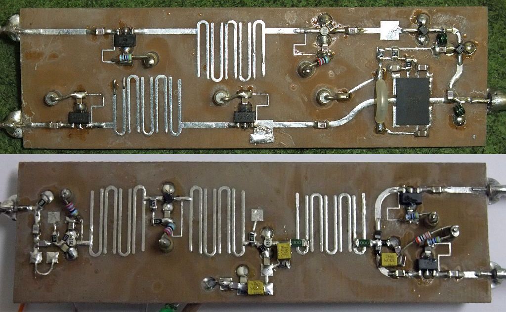
The RF head an mixer are built on two microstrip printed-circuit boards etched on 0.6mm-thick FR4 laminate. The latter introduces losses especially in the bandpass filters that have to be compensated by the MMIC amplifiers. On the other hand, a lossy laminate helps to avoid unwanted millimeter-wave oscillations of HEMTs. Microstrip bandpass filters with unsymmetrical frequency response are used as appropriate:
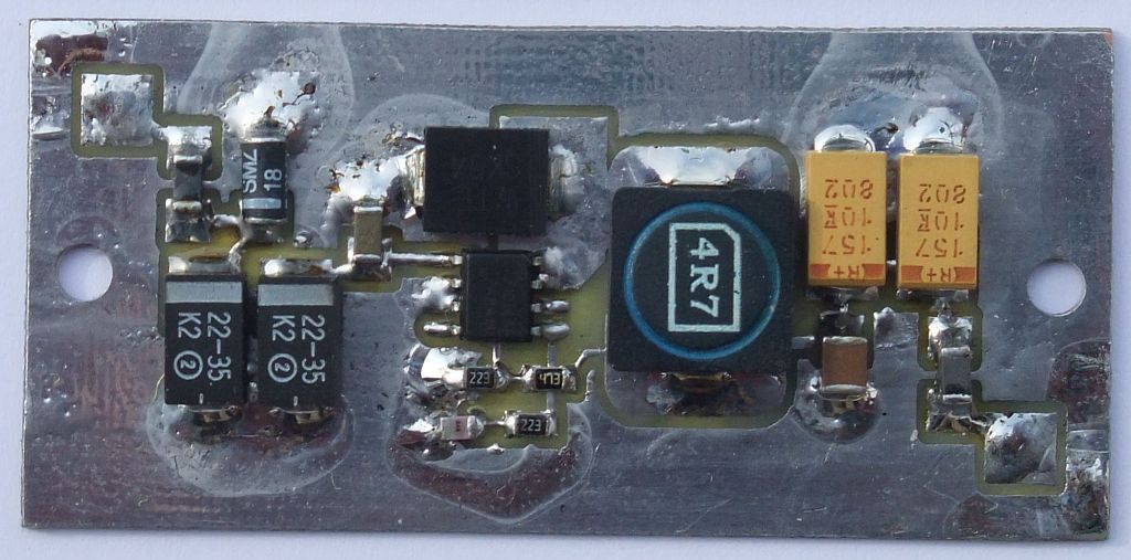
IF-driven RX/TX switching uses the same circuit as in the 13cm version. Both transverters use a switching regulator for the +5V supply with an AOZ1014 or AOZ1017 chip:
Both microstrip modules and the frequency synthesizer are installed in three brass frames for shielding:
The whole 9cm transverter is 125mm wide, 150mm deep and 30mm high including a switching power regulator for +5V:
The shape of the printed-circuit boards is selected to avoid unwanted resonances in the frequency range below 5GHz. The brass frames therefore only require covers from thin copper sheet while microwave absorber foam is not required:
A much more detailed description of the BPSK transverter for 3405MHz including all circuit diagrams is available in the following PDF document. The corresponding design files including printed-circuit boards and firmware for the CPLD are included in the following ZIP archive:
BPSK transverter for 3405MHz description (SLO)
BPSK transverter for 3405MHz filesPractical experiments show that the receiving section of the described BPSK transverter for 3405MHz offers similar sensitivity and interference rejection as the 2360MHz version. The transverter spurious emissions are 40-50dB below the desired signal at 3405MHz and can be totally eliminated with an external cavity filter.
6. ZIF-BPSK RTX for 1245MHz 10Mbps
Both transverters for 2360MHz and 3405MHz allowed a simple migration from ATNC/EATNC data rates of 1.2288Mbps or 2Mbps up to the RATNC/SATNC data rates of 10Mbps and more. Unfortunately transverters and their corresponding IF transceivers are a complicated solution that requires lots of work for assembly. A much simpler BPSK-ZIF transceiver for 1245MHz 10Mbps was attempted first:
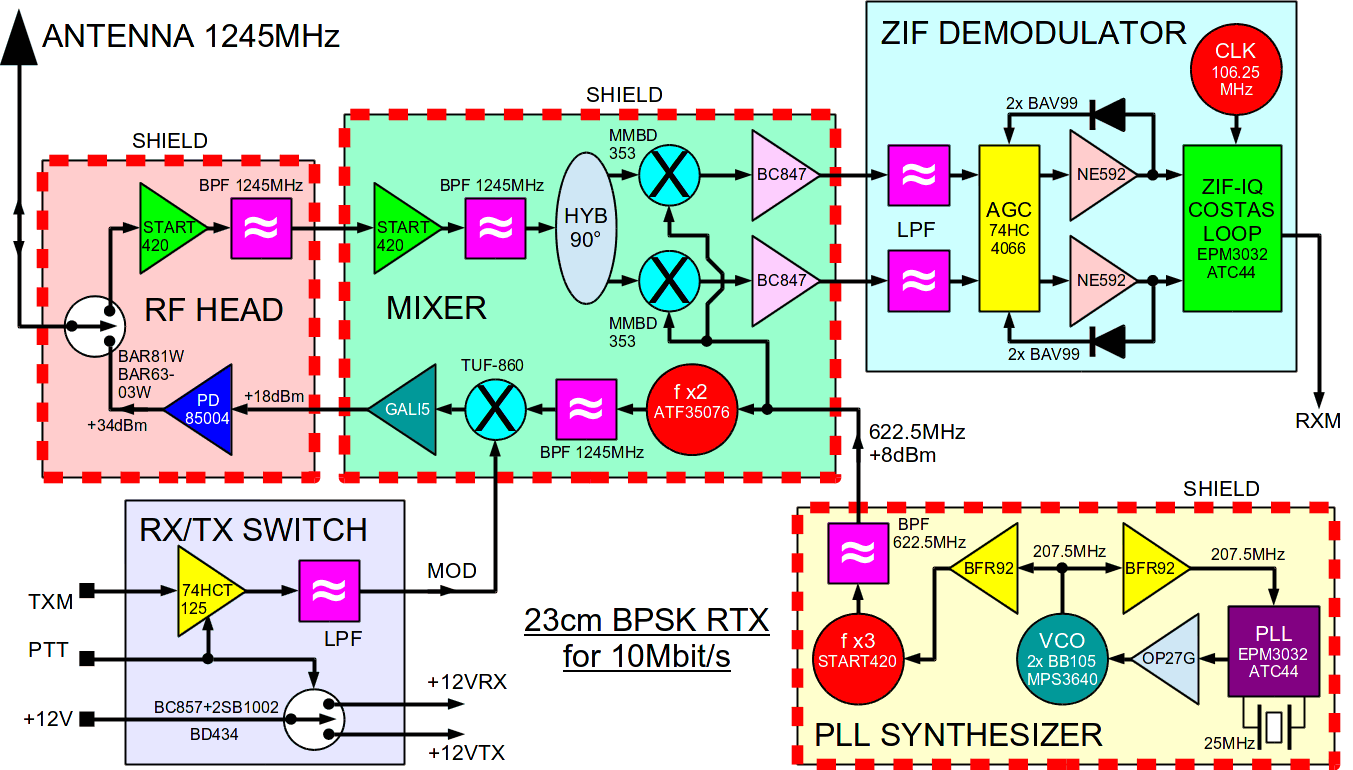
The first prototypes of the BPSK-ZIF transceiver for 1245MHz 10Mbps used the RF head from the old 23cm ZIF-BPSK transceiver from 1996. Thanks to the higher drive, the CLY5 power GaAsFET provided up to 1W or 1dB more output power than the 1996 radio. A new RF head with the PD85004 power LDMOS provides around 2.5W on the antenna connector. An additional advantage of the PD85004 is its 12V supply voltage. Thanks to the much improved efficiency, the overall current drain of the PD85004 version is not higher than the old CLY5 version.
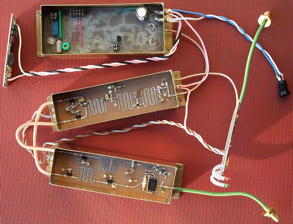
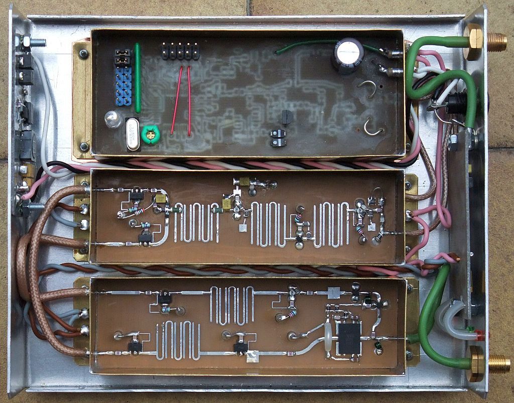
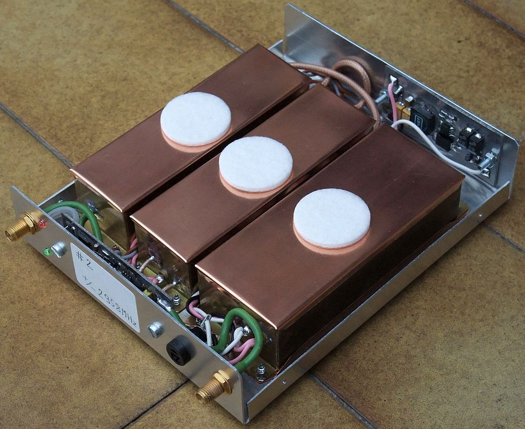
The new ZIF-BPSK RTX for 1245MHz 10Mbps is described in detail in 23cm BPSK RTX za 10Mbit/s (SLO - 23cm BPSK RTX for 10Mbit/s NBP packet-radio) and includes just three shielded modules:
The new ZIF-BPSK RTX for 1245MHz 10Mbps was found to have excellent practical performance, allowing line-of-sight links of up to 150km with relatively small-size antennas (30cm) and up to 20km with the same small antennas and first Fresnel zone obstructed!
7. 10Mbps BPSK ZIF transceivers for 1.2GHz, 2.3GHz and 3.4GHz
Integrated components allow building smaller and simpler radios with less stringent RF shielding requirements. For example, a discrete quadrature mixer required in any ZIF receiver may require a local-oscillator drive level of about +10dBm. A monolithic quadrature mixer may work with a local-oscillator drive level of just -20dBm. Therefore an integrated solution may require 30dB less shielding than a discrete solution for the critical local-oscillator leakage into the RF stages of a ZIF receiver.
Unfortunately most available integrated components are strictly built for multicarrier OFDM operation and are difficult to use with other modulations. The AD8347 Zero-Intermediate-Frequency receiver chip is universal enough to build any kind of radios including analog receivers. Together with the companion modulator AD8349 and a suitable frequency synthesizer like the ADF4351 or MAX2870 it makes the core of a compact BPSK transceiver for any frequency up to 3GHz and even beyond:
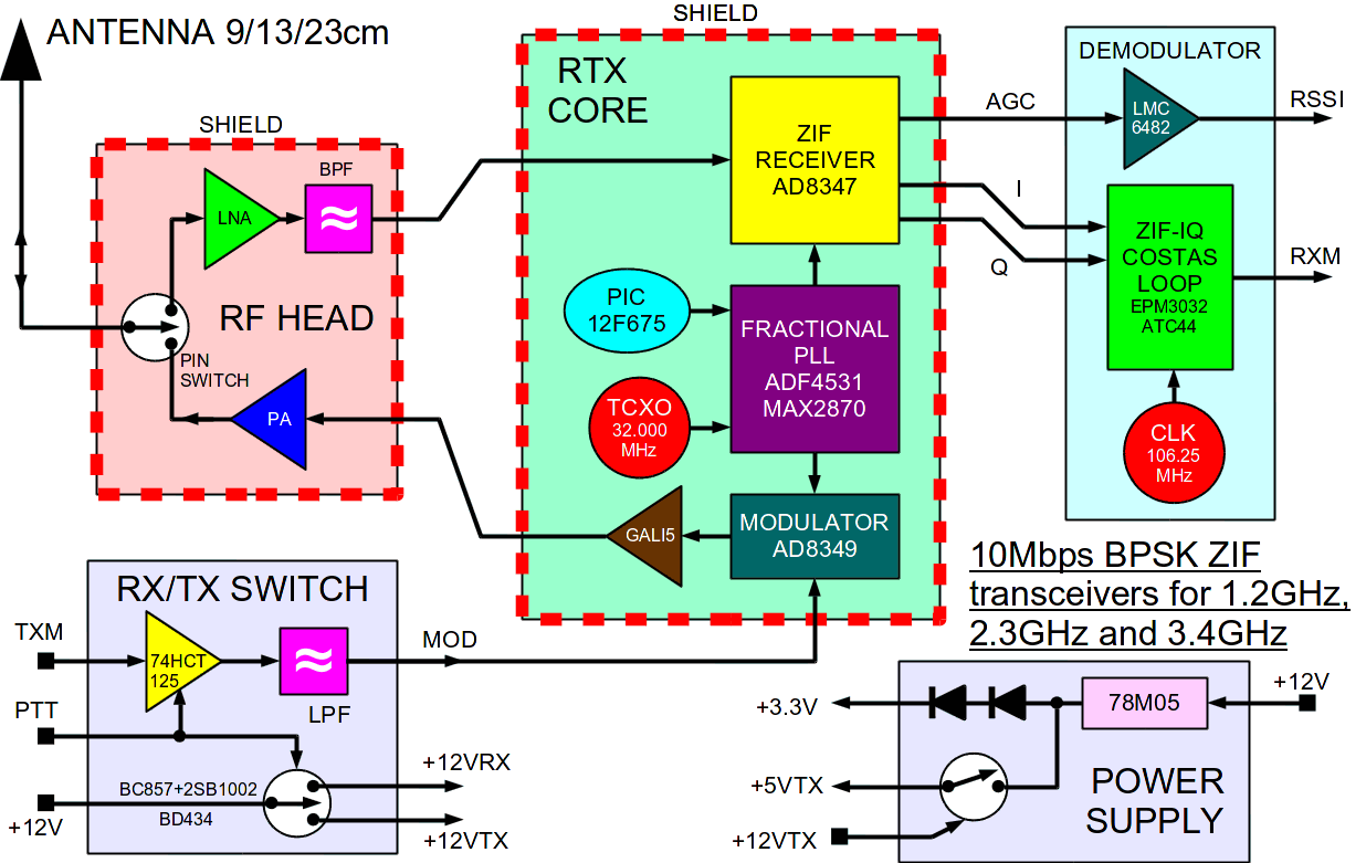
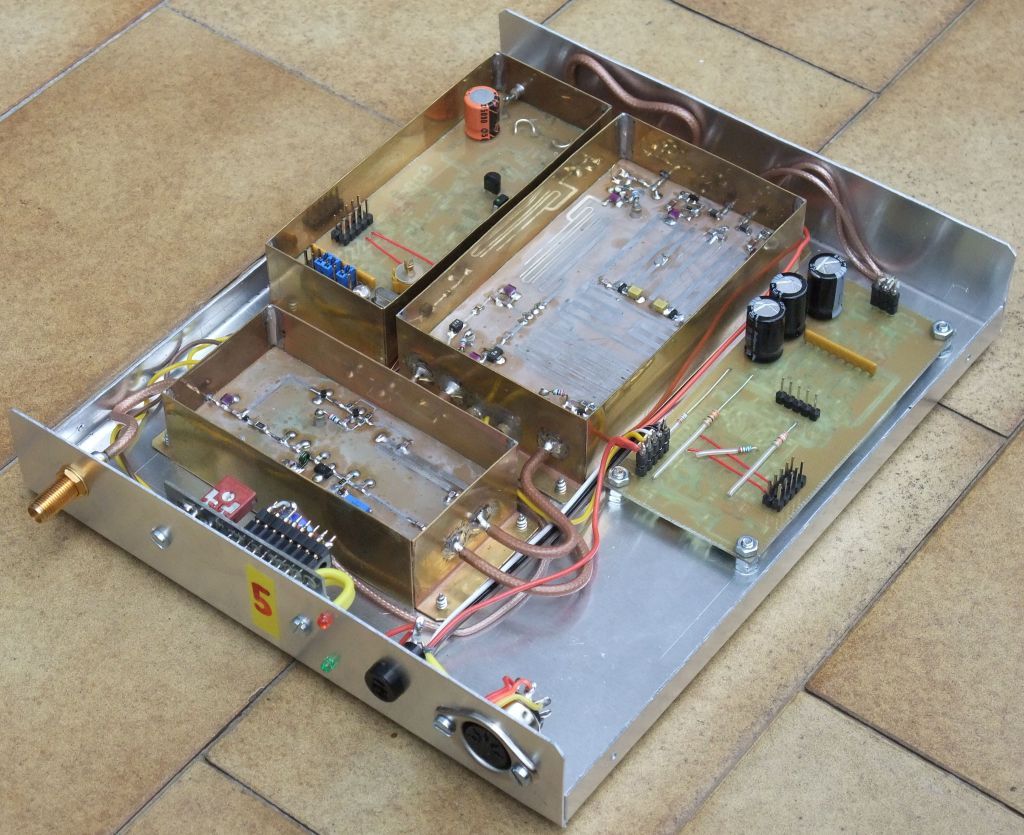
In particular, three BPSK transceivers for the 9cm, 13cm and 23cm amateur allocatons were developed, built and tested. All three transceivers are 170mm wide, 120mm deep and 30mm high and only differ in the RF head and related supply:
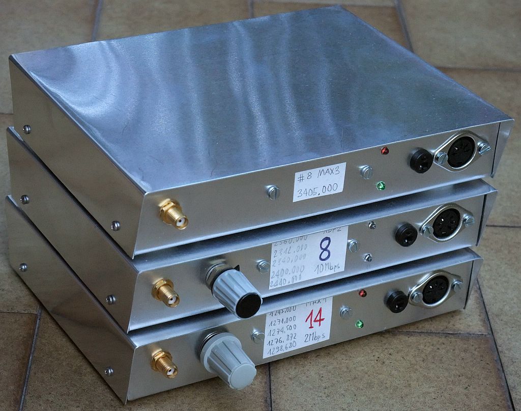
Although the AD8347 ZIF receiver is only specified up to 2.7GHz, it was found to provide excellent quadrature and gain at 3.4GHz. Unfortunately the output power of the companion modulator AD8349 drops above 2.5GHz requiring more amplification in the transmitting chain. The ALM32320 HEMT device provides about 2.5W of output power at 3405MHz while requiring an inefficient +5V supply. The 10Mbps BPSK ZIF transceiver can only use a single channel at 3405MHz in the narrow 9cm amateur allocation. Therefore it does not need a channel-selection switch:
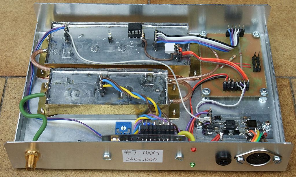
The shielding of the two RF modules: RF head and RTX core is simplified so that expensive and difficult-to-get feed-through capacitors are not needed. The particular radio shown below is designed for 13cm and has a 5-channel selector. A PTFC270101M power LDMOS provides about 3W of output power at 2360MHz at a supply voltage of +12V. This particular radio is equipped with a switching +3.3V power supply to decrease the current drain to about 100mA at +12V while receiving:
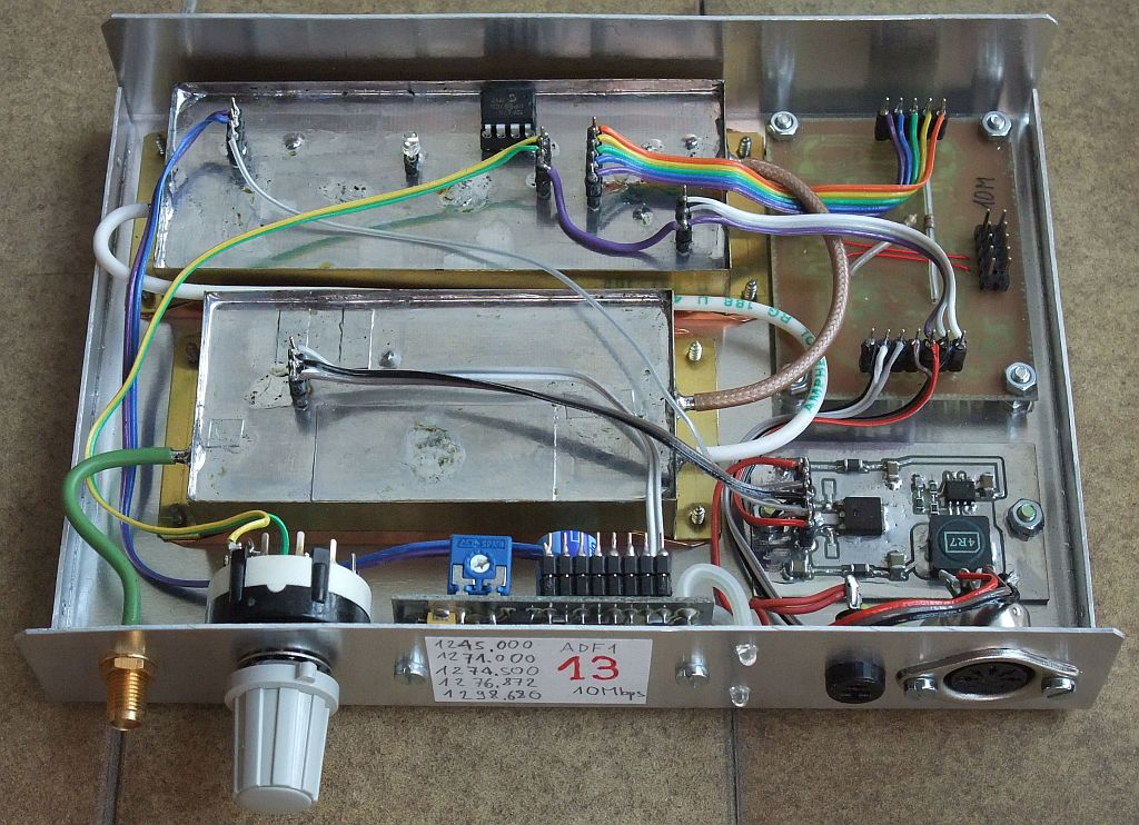
Tinned iron sheet can also be used in place of brass for shielding. The particular radio shown below is designed for 23cm and has a 5-channel selector. A PTFC270101M power LDMOS provides about 4W of output power at 1245MHz at a supply voltage of +12V. Narrower filters are built in to optimize the radio for 2Mbps operation:
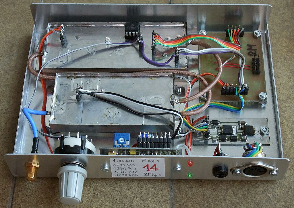
A detailed description of all three radios is available in: 10Mbps BPSK ZIF transceivers for 1.2GHz, 2.3GHz and 3.4GHz
Comparing different BPSK radio designs shown on this page, all achieve a similar receiver sensitivity. The power consumption while receiving at +12V is in the 250...300mA range for all designs without using switching voltage regulators. On the other hand, the power and efficiency of the transmit chain strictly depend on the semiconductor devices used.
A traditional ZIF receiver design with discrete components achieves the best RF dynamic range. Transverters increase the RF gain and decrease the dynamic range. Unfortunately the AD8347 has a very high RF gain resulting in a poor RF dynamic range. A very effective countermeasure is to use narrow bandpass filters in the antenna line in all cases!
Simple and efficient bandpass filters are descibed in: Practical cavity filters for the frequency range 1GHz...4GHz