(THEORY)
(ANALOG)
(DIGITAL)
(SOFTWARE)
(HOME)
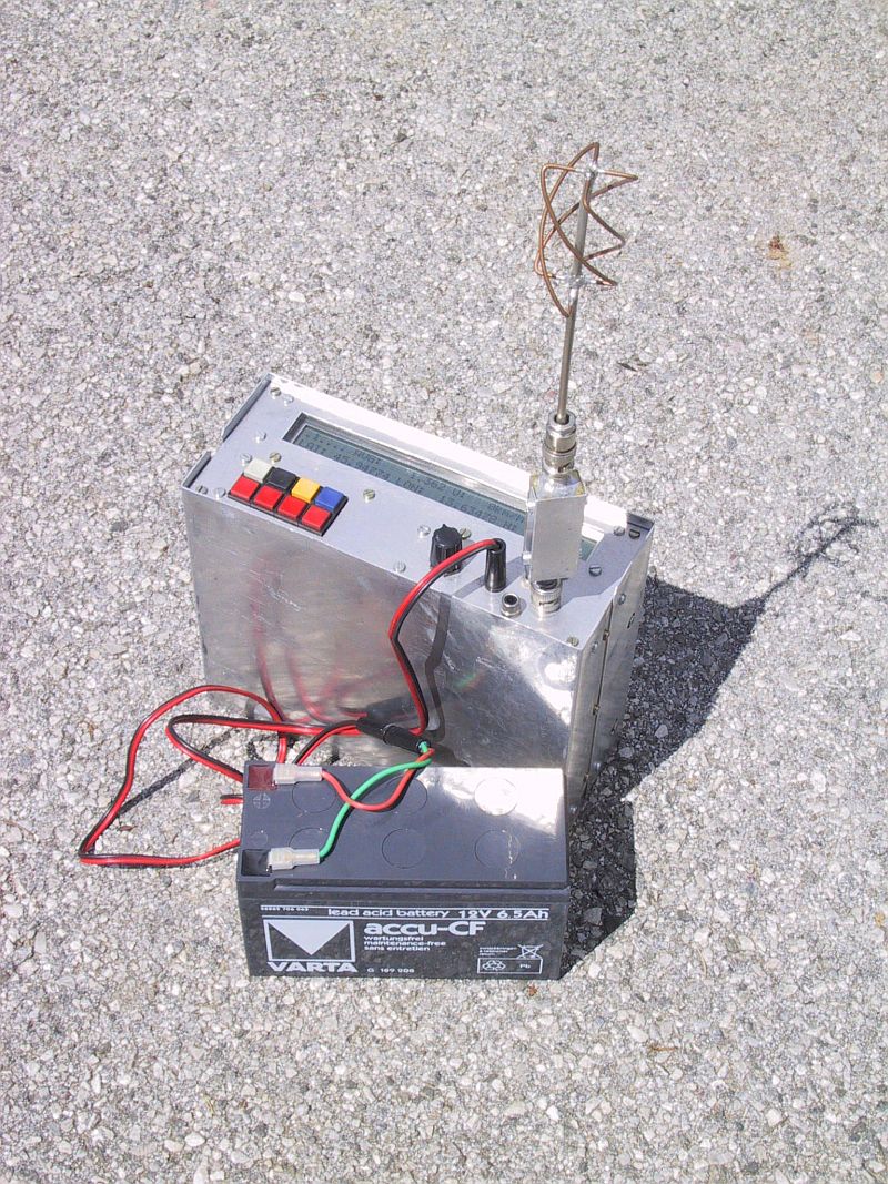
A homemade receiver for GPS & GLONASS satellites
Matjaz Vidmar, S53MV (ex YU3UMV, YT3MV)
5. GPS & GLONASS receiver software
5.1. GPS/GLONASS receiver software overview
Satellite navigation is one of the first applications
that totally depends on the availability of suitable computers
and the corresponding software. Although initially the digital
computer was only intended to solve the navigation equations,
other tasks were being gradually added to simplify
the hardware in front of and behind the computer itself.
In the described GPS/GLONASS receiver even most of the signal
processing is performed in software, just to keep the analog
front-end and dedicated DSP hardware as simple as possible.
The software running in a GPS or GLONASS receiver is
therefore very complex and includes a variety of very
different functions. For example, digital signal processing
requires quick but simple integer arithmetics while solving
the navigation equations requires high-accuracy floating-point
arithmetics. The latter does not need to be as quick as the
former signal processing, but a considerable number of
operations still need to be performed in a limited amount of
time.
To make a fair comparison one should consider the
development time for the hardware and for the software.
In the case of the described navigation receiver, the
development of the software required between two and three
times the amount of time required to develop the hardware!
Unfortunately it is much more difficult to describe down
to the smallest detail the software than the hardware. For the
hardware one can draw the circuit diagrams and prepare
detailed parts lists. On the other hand, detailed descriptions
of the software tend to become boring and minor details tend
to hide the real problem being solved.
Therefore only the major functions performed by the
software will be described in this article. These include
signal acquisition and processing, almanac and precision
ephemeris data collection, time and frequency measurements,
solving the navigation equations and data display in a
suitable format for the user. At the end the user interface:
display menus and user commands, will be described in detail.
The overall software is written in different languages
due to the differing functions to be performed: MC68010
assembly language, DSP computer high-level language and even
directly in machine code.
The digital signal processing software is written in
the MC68010 assembly language. The corresponding file has
the extension .ASM. This file is first compiled into machine
code and then into hexadecimal format, so that it can be
easily inserted in the DSP computer high-level language.
The orbital mechanics and navigation equation part is
written in the DSP computer high-level language. The latter
supports a floating-point format with a 32-bit mantissa and
a 16-bit exponent. A 32-bit mantissa is generally sufficient
considering the accuracy of the data obtained from the GPS
or GLONASS satellites. The corresponding file has an extension
.SRC and can be compiled into an .EXE file and executed on a
DSP computer equipped with the described dedicated DSP
hardware board, but with an unmodified CPU board!
In a portable GPS/GLONASS receiver all of the software
is stored in a 27C256 EPROM. The latter includes a starting
program, the high-level language compiler and a version of
the .SRC file with all of the comments and other unnecessary
symbols removed. When the portable receiver is turned on,
the program will be compiled in the RAM. This operation
takes around 10 seconds and is necessary to save EPROM space,
since the compiled program in the RAM takes around 100kbytes.
The present discussion applies to the current software
versions V122 (GPS) or V39 (GLONASS). When running the
software on a DSP computer, the type of display may be
selected by the TOTAL/PARTIAL RESET switch while starting
the program: switch open (TOTAL RESET) selects the LCD
while switch closed (PARTIAL RESET) selects the CRT display.
Of course the LCD can only be selected in a stand-alone,
portable receiver and the corresponding input on the CPU
board MUST BE LEFT OPEN!
5.2. Real-time tasks: signal acquisition & processing
The signal acquisition and processing tasks run under the
1kHz interrupts requested by the dedicated DSP hardware
module. The tasks include the multiplexing of the
single-channel hardware among four different satellites,
the C/A-code synchronization acquisition and tracking,
the carrier lock acquisition and tracking, the 50bps
navigation-data demodulation, bit synchronization and frame
synchronization with parity check and finally the averaging
of the measured code phase, code rate and carrier frequency.
After an interrupt request is received from the dedicated
DSP hardware, the interrupt-servicing routine will first latch
the content of all of the counters in the dedicated hardware.
It will then read the latched content and reset and arm the
interrupt request flip-flop. The hardware counters are never
reset. The actually integrated value is computed from the
difference between the actual counter content and the previous
sample content. The four differences are further normalized
using the result from the reference 1ms divider. Finally,
the interrupt-servicing routine also increments a 32-bit
millisecond counter, which is later used to relate the
measurements to the 50bps navigation data.
The single-channel hardware is multiplexed among all of
the satellites received. However, due to the limitations of
the hardware, switching to another satellite will corrupt
one millisecond of data. Therefore, the basic multiplexing
period includes one millisecond to switch the hardware
followed by 8 milliseconds to collect the data from a given
satellite. After this 9-millisecond period the hardware is
switched to another satellite. The multiplexing rate is
therefore 111 hops per second.
The multiplexing rate and especially the multiplexing
sequence have to be chosen carefully. The navigation data
is transmitted at a speed of 50bps, so one bit is 20ms long
and lasts exactly 20 interrupt periods. If the navigation data
is to be collected from a given satellite, then this satellite
should get at least a few 1ms samples of data from each 20ms
bit period. Further, the multiplexing period should not be an
integer submultiple of the bit period, so that the bit
transitions can be detected.
Considering the limitations of the single-channel
hardware, the multiplexing sequence can not allow collecting
the navigation data from more than two satellites at a time.
In practice, since four satellites need to be received for a
navigation solution, the navigation data can only be collected
from a single satellite at a time using half of the
single-channel hardware time. The remaining hardware time
is split among the remaining three satellites. The privileged
satellite that gets more hardware time of course needs to be
periodically exchanged to allow collecting the navigation data
from all four satellites.
There is yet another constraint on the multiplexing
sequence. If a certain satellite only gets a few sampling
periods, then false locks of the carrier recovery loop
become very likely. In order to avoid this, the following
multiplexing sequence is used in the described GPS/GLONASS
receivers (1 = privileged satellite, 2, 3 & 4 = others):
121213141412131314
121213141412131314
...
The complete multiplexing sequence therefore repeats after
18 multiplexing periods or 162 milliseconds.
The C/A-code synchronization is always obtained from the
signal magnitude obtained from the dedicated hardware. The
signal phase information is intentionally not used for this
purpose since the carrier phase lock is a much more critical
operation. Therefore, for the C/A-code synchronization, the
early and late magnitudes are computed from the related I and
Q sums for every 1ms accumulation period. These sums are then
averaged over the 8 milliseconds containing valid data in a
9-millisecond multiplexing period.
The initial state of the receiver is unlocked and the
C/A-code synchronization acquisition has to be obtained first.
The hardware variable delay will therefore be scanned through
all possible C/A-code phases (1023 for GPS and 511 for
GLONASS) by incrementing the variable-delay counter in suitable
steps (6 for GPS or 9 for GLONASS). When a signal magnitude
above threshold is detected, the software switches to the
synchronization maintaining routine. A suitable time constant
is built-in to prevent the loss of lock on short signal
interruptions. In the synchronization-tracking mode, the
software performs as a second-order phase-locked loop,
computing the C/A-code phase and rate from the measured
early-minus-late difference.
The signal carrier still includes the 50bps 0/180 BPSK
navigation data, so a Costas-loop demodulator is required
to obtain both the regenerated carrier for doppler
measurements and the 50bps navigation data. The Costas-loop
demodulator operates on every 1ms signal sample I & Q
components computed as an average of the early/late data.
The loop feedback is a second-order network computing the
carrier phase and frequency.
The carrier-lock operation is not simple. Initially,
the whole frequency range from -500Hz to +500Hz is
scanned. To prevent false locks, the scanning is stopped
only when the residual loop error becomes small enough.
Finally, the locking point needs to be checked for the
+/-500Hz ambiguity caused by the 1kHz sampling rate. The
latter ambiguity is resolved by counting the number of
transitions in the demodulated data stream in every
8 milliseconds of valid data in a multiplexing period. Since
valid GPS data only has transitions every 20ms (GLONASS
every 10ms), there can be at most one transition in 8ms
of data. If the frequency is wrong, there are at least 6
transitions and this can be detected easily.
Of course, the phases of both code and carrier PLLs
need to be adjusted for the following multiplexing period,
accounting for all of the time spent by the hardware
processing the signals from other satellites.
In a navigation receiver the code phase and the carrier
frequency are the main parameters to be measured and these are
supplied by the corresponding phase-locked loops. In addition
to this, the code rate is also used by the software to
compute a rough approximation for the carrier frequency and
eliminate the ambiguity caused by the 1kHz signal sampling
rate. Before further processing, the code phase, code rate and
carrier frequency are averaged over 16 multiplexing periods
corresponding to a time span of 288ms (privileged satellite)
or 864ms (other satellites). The averaged measurements are
placed in a FIFO memory together with 1ms time tags, to be
read by the main program.
The last task performed by the interrupt routine is
navigation data processing. The latter includes yet another
PLL for bit synchronization. This PLL locks on the transitions
in the data stream. The demodulated 1ms samples containing
the transitions are rejected while all of the other available
samples for a given satellite are accumulated into bits (GPS)
or half-bits (the GLONASS manchester phase is not known yet).
The following navigation data processing depends on the
data format and this is slightly different between GPS and
GLONASS. The GPS data is formatted into 30-bit words
containing 24 true data bits and 6 parity-check bits. The word
synchronization is obtained by checking the parity bits,
including the last two bits of the previous word, for any
possible word phase. The BPSK polarity ambiguity is also
resolved by the parity bits. The synchronized and checked
GPS data words are placed in another FIFO memory together with
1ms time tags, to be read by the main program.
The GLONASS data is formatted into lines with 85 data
bits in manchester format and a non-manchester sync pattern,
for a total duration corresponding to 100 bits. The sync
pattern is not used in the described GLONASS receiver. The
synchronization is obtained by checking the 8 parity bits for
any possible half-bit phase (200 possible phases), to resolve
the manchester phase ambiguity as well. Since the data bits
are differentially encoded, there is no polarity ambiguity to
be resolved. Like in the GPS receiver, the correctly received
data lines are placed in another FIFO memory together with 1ms
time tags, to be read by the main program.
5.3. Main program loop tasks
Since most of the functions performed by the main program
loop require high-accuracy floating-point arithmetics, the main
program is mainly written in the DSP computer high-level
language. Of course all of the interfaces to the interrupt
routine and to the various peripherals (initialization of the
dedicated DSP hardware, LCD drive, real-time clock chip) are
at least partially written directly in the MC68010 machine
code and are inserted in hexadecimal format in the program
source code.
The main program loop executes once for every new set
of averaged measured data. The latter is available every
864 milliseconds for the three satellites that get less
hardware time. The privileged channel supplies three
separate sets of averaged data in the same time period, but
the excess data is not used by the main program loop.
The main program loop also updates the LCD or writes a
new line on a CRT display. The internal operation of the
program is however independent of the selected menu on the
display. The menu only affects the keyboard functions and
some computations closely related to the format of the
displayed data, like coordinate conversions.
The first task of the main program loop is to write the
look-up tables in the dedicated DSP hardware memory. This
operation is done at receiver power-up, when changing
satellites, when adjusting the carrier frequency (in 1kHz
steps) or when switching the privileged satellite. The
satellites can be selected manually, but usually the software
is set to automatically select visible satellites.
When a given satellite is selected, the receiver
requires some time to lock on its signal. The software will
first look for all possible C/A-code phases. If the lock is
not achieved, the main program loop will change the hardware
look-up table frequency in 1kHz steps in a given frequency
range (20kHz in the GPS receiver or 25kHz in the GLONASS
receiver). Of course the look-up table frequencies for all
four satellites can also be preset manually.
The look-up tables are rewritten when switching the
privileged satellite for several reasons. When all four
satellites have been acquired, this happens every minute,
synchronized to the major data frames transmitted every 30
seconds from both GPS and GLONASS satellites. Since switching
the privileged satellite includes some loss of data, other
operations that corrupt the data, like rewriting the look-up
tables, may be performed at the same time without any
additional losses. The look-up tables are rewritten to correct
for large variations of the doppler shift or local reference
oscillator drift. Further, the new look-up tables are
rewritten with a randomly chosen phase relationship between
the carrier phase and code phase, to avoid any possible
interferences between the carrier and the code when averaging
the measured data over a longer period of time.
The main loop will then process all of the navigation
data accumulated in the corresponding FIFO memory. The
software looks for the frame sync and formats the data into
frames. Additional checks are made before the formatted
data is used. Correctly received frames are used to collect
the precision ephemeris orbital data for the given satellite,
to update the almanac containing less accurate data about the
whole satellite navigation system and to set the GPS/GLONASS
receiver real-time clock chip.
The next task is to collect the code phase and carrier
frequency measurement results from the corresponding FIFO
memory. The most recent data is always used together with the
previous sample to relate all of the data to a single time
point using linear interpolation. This simplifies the
following computations, since the positions and velocities
of all four satellites need to be calculated for a single
point in time.
The measured data and the satellite positions and
velocities (computed from the precision ephemeris data) are
then assembled into the navigation equations. A set of
three time-difference navigation equations is obtained from
code-phase differences and another set of three
doppler-difference navigation equations is obtained from
carrier-frequency differences.
The time-difference navigation equations are solved
first, using the Newton's method. The starting point is taken
in the Earth's center (x=y=z=0). From this starting point
the Newton's method requires between three and four iterations
to converge to the final result for a user located on the
Earth's surface. The result in Cartesian coordinates x,y,z
is then converted to longitude, latitude and height.
The position obtained may now be corrected for the
propagation anomalies in the ionosphere and troposphere.
The present software does not apply any correction for the
ionosphere. The navigation equations are only corrected for
the troposphere at the calculated height and the Newton's
method is iterated once again to obtain the final result.
Since the position is already available from the
time-difference navigation equations, the doppler-difference
navigation equations are solved to obtain the velocity of
the user. Solving the doppler-difference equations for the
velocity does not require a numerical iterative method, since
the equations result linear for this unknown. The computed
velocity vector is converted into magnitude, azimuth and
elevation on the display.
The accuracy of the navigation solution depends on the
geometry of the satellites. In place of the GDOP the software
only computes the determinant of the linearized system of
equations at the calculated position. This determinant is
a dimensionless quantity. The higher the determinant, the
more accurate the solution. If the determinant is too low,
an error condition is signalled. The doppler-difference
equations have the same determinant if solved for velocity.
The main program loop also performs data averaging.
Both position and velocity are averaged. Only good data
with no error signalled is added to the average. The
determinant of the system of equations is used as a weight
for each new data set added to the average. Of course the
averaging buffer may be manually reset if desired.
The display includes several different menus and two
of them are devoted to the immediate and averaged data. The
position may be displayed in different formats: degrees
only, degrees, minutes and seconds or Gauss-Krueger
rectangular grid. Other menus are used to show the receiver
status and the almanac data.
Finally, the main program loop usually also performs an
automatic satellite selection. This function is triggered
if an error condition is signalled continuously for a certain
period of time (100 main loops). The software then uses the
almanac data and the real-time clock to find the visible
satellites at the averaged user location. The receiver is
then programmed for the four visible satellites with the
highest elevations on the sky. Although this procedure does
not yield the best GDOP, its operation is foolproof.
5.4. Software menus and commands
Since a portable GPS/GLONASS receiver only has a small
keyboard with a few keys and a small alphanumeric display,
the various user commands need to be arranged into several
different menus. The organization of the commands in the
different menus is shown on Fig. 62.
The keyboard has 8 different keys. Four of them
(corresponding to ASCII characters "4", "5", "6" and "7") are
used to select the four main menus. Depressing these keys
only changes the content of the display and the functions of
the other keys, but does not affect the internal operation
of the GPS/GLONASS receiver. Some of these keys have
additional functions if depressed more than once. Depressing
key "4" cyclically shows all four virtual receiver channels
(satellites) on the display. Depressing key "7" cyclically
shows the general receiver status and the almanac data for
all currently visible satellites.
The remaining keys (ASCII "0", "1", "2" and "3") are
called parameter keys. Depressing these keys affects the
internal operation of the GPS/GLONASS receiver as a function
of the current menu. The mode of operation of these keys is
also dependent on the actual menu. Some functions allow a
repeated action of these keys during just one main program
loop (864ms), like setting the channel IF. Other functions
are intentionally slowed down, like the total reset of the
receiver. The latter requires depressing the corresponding
key for at least 9 times and just one entry is allowed for
each main program loop, to avoid unintentional loss of data.
In order to understand the commands of a GPS/GLONASS
receiver it is necessary to understand the internal operation
of the latter. A GPS/GLONASS receiver includes a nonvolatile
RAM to store the almanac data and a real-time clock that
are always powered by a small internal NiCd battery. The
nonvolatile RAM is used to store the almanac data and the
approximate user position as a result of previous receiver
operation. At power-up this data is used together with the
real-time clock data to find all visible satellites and
speed-up the acquisition of four usable satellite signals.
When a GPS or GLONASS receiver is first powered up,
all of the nonvolatile RAM contains random data and a total
reset is required. The total reset erases all almanac data
and puts the receiver in the manual satellite select mode.
All receiver virtual channels are set to a central carrier
frequency and GPS PRN#16 or GLONASS CHN#13. The menu "4"
is selected to show the virtual channel #1 data.
The initial satellite signal acquisition without any
almanac data may take a large amount of time, especially in a
single-channel receiver. The receiver does not know which
satellite to look for nor its frequency offset caused by the
doppler shift and by the unknown frequency drift of the
receiver itself. The current software for the described
GPS/GLONASS receiver is not able to select different
satellites automatically without any almanac data, so this
has to be done manually.
After manually selecting the satellite(s), the software
is going to try to achieve C/A-code lock. If the latter does
not occur on the given IF frequency, the receiver is going to
scan the expected IF frequency range in 1kHz steps by writing
the corresponding look-up table. Only the privileged satellite
IF is scanned in the range from 2310kHz to 2330kHz (GPS) or
from 1675kHz to 1700kHz (GLONASS).
While searching for the initial signal acquisition there
is a small difference between the GPS and GLONASS receivers.
The GPS constellation is now complete and more than four
visible satellites can be found at any time, so the GPS
receiver is only going to switch the privileged channel after
a satellite signal is acquired. On the other hand, the GLONASS
constellation is not complete and sometimes there is just one
visible satellite, so the GLONASS receiver is going to try
a different virtual channel with a different satellite if the
current privileged satellite was not acquired.
After a satellite signal has been acquired, the key "4"
menu shows the most important receiver parameters:
RX:    virtual channel number
SV:    GPS satellite PRN code number
CH#    GLONASS satellite RF channel number
CF:    look-up table preset central IF frequency (kHz)
R:     measured IF frequency (kHz, from code rate)
S:     signal level (S-meter)
SVH:   satellite health flag (0=OK)
URA:   GPS user range accuracy (m)
ASF:   GPS anti-spoofing flag (0=OFF)
En:    GLONASS ephemeris upload age (days)
AOE:   GLONASS ephemeris age (s)
If the receiver has been turned on for the first time or
has not been used for a considerable period of time (more than
one week), the best thing to do is to collect the complete
almanac data first. To speed-up the almanac data collection
it is recommended that the remaining three receiver virtual
channels are set to the same satellite and to the same IF
frequency as the channel that already acquired a satellite.
After all four virtual channels achieved signal lock, the
almanac data collection takes 12.5 minutes for GPS or
5 minutes for GLONASS, since the GLONASS receiver does not
make use of half of the almanac frames.
The accumulated almanac data can be checked by repeatedly
pressing key "7". The almanac data includes the satellite
name/number plus the following information:
CH#    GLONASS RF channel number
EL:    elevation (degrees)
AZ:    azimuth (degrees)
DF:    doppler frequency shift (Hz, polarity as in the IF)
A/E    GPS almanac/precision ephemeris data
SVH:   satellite almanac health flag (GPS 0=OK, GLONASS 1=OK)
ASF:   GPS anti-spoofing & configuration flag
UTC:   UTC date and time
The elevation, azimuth and doppler shift are computed for
the reference user position as obtained from the averaged data.
After a total reset this reference position is set in central
Europe. Checking the almanac it is possible to find out when
the receiver can be switched to automatic satellite selection.
In the automatic satellite selection mode, the program selects
the four satellites with the highest elevations and sets the
corresponding central IF values in the hardware look-up tables.
This selection can be done immediately by pressing key "0" in
menu "7" or by switching the program to do this automatically
after a period of bad data (key "3" in menu "7").
After four satellites have been acquired, the display may
be switched to menu "5" or "6", to show respectively the
immediate or averaged data. These menus show the following:
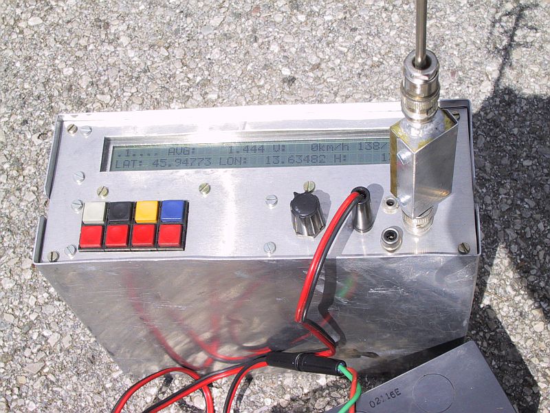
DET:    determinant of the system of equations (menu "5" only)
AVG:    averaging weight (menu "6" only)
V:      velocity vector magnitude (km/h), azimuth & elevation
LAT:    latitude (degrees or m, north)
LON:    longitude (degrees or m, east)
H:      height above ellipsoid (m)
At the beginning of all menus (except the almanac) the receiver status error codes appear, as shown on Fig. 63. These codes show the general receiver status, the current privileged virtual channel and the status of the single virtual channels. Most of the codes used are obvious, but three of them require further explanation. In the general receiver status, code "P" means that the computed position deviates too much from the previous main program loop. On the other hand, code "E" is only activated after the averaging weight gets larger than 5 and means that the equations themselves deviate too much from the already computed average position. Finally, code "T" in the virtual channel status appears quite frequently since the current software does not handle the overflow of the C/A-code variable-delay counter correctly.
Finally, the general status menu (key "7") shows some
interesting data about the receiver: the satellites currently
selected, AUTomatic or MANual satellite selection, the
measured nominal IF frequency of the receiver (without the
doppler shift), the measured receiver master oscillator
frequency and the UTC date and time.
6. Conclusion
The GPS and GLONASS systems are mainly intended for
navigation, but there are many other less advertised but not
less important nor less interesting applications of these
systems. Since these systems are known and the technology to
use them is available to anyone, we radio-amateurs should
consider our own applications of these systems [13].
Although the navigation itself is not of much interest to
radio-amateurs, it would probably make much more sense to
transmit GPS or GLONASS coordinates of a contest location
rather than the inaccurate EU or WW locator, which is
already not accurate enough for serious microwave or laser
communications. By the way, GPS and GLONASS use almost the
same coordinate system and a long time average shows
differences in the order of only 10m between the two
systems.
A side product of both GPS and GLONASS is accurate
time and frequency broadcast. In order to achieve the
specified navigation accuracy, the timing measurements have
to be performed to an accuracy of about 10ns. The same
requirement applies to the on-board satellite atomic clocks.
The final user time transfer accuracy ranges between 30ns
and 100ns, depending also on the knowledge of the exact user
location. Thus the user should also compute his position
even if he only needs accurate time.
Radio-amateurs could use this time transfer capability
of both GPS or GLONASS every time when accurate synchronization
is required. Coherent communications are just an example, the
accuracy of GPS or GLONASS offers more than this: for example,
the actual propagation path of the radio signal and the
propagation mechanism could be investigated in this way.
The frequency broadcast accuracy of both GPS and GLONASS
is in the range of 10^-12, far better than can be achieved
with HF or LF standard frequency transmitters. The accuracy
of the latter is limited to around 10^-7 by the propagation
effects alone, and this is not enough for serious microwave
work. GPS and GLONASS are also available globally 24 hours
per day and are not limited by the transmitter range,
propagation effects or low-frequency electronic pollution.
Finally, GPS and GLONASS represent a step away from
being just an operator of black-box amateur-radio equipment.
Although there are several ready-made GPS receivers on the
market, we will probably have to develop our own receivers
for our experiments, both the hardware and the software.
Building such a receiver may be an interesting challenge as
well. The receiver shown in this article is perhaps just
the first step, other related projects or better receivers
will hopefully follow soon.
7. References
  [1] Matjaz Vidmar: "Digitale Signalverarbeitungs-Techniken
      fuer Funkamateure, Teil 2: Ein DSP-Computer fuer
      Amateurfunk-Anwendungen",
      pages 2-25/1-89, UKW-Berichte/VHF-Communications.

  [2] Matjaz Vidmar: "Digitale Signalverarbeitungs-Techniken
      fuer Funkamateure, Teil 3: Bau und Inbetriebnahme des
      Computers",
      pages 66-88/2-89, UKW-Berichte/VHF-Communications.

  [3] Jonathan S. Abel, James W. Chaffee: "Existence and
      Uniqueness of GPS Solutions",
      pages 952-956/6-91, VOL.27, IEEE TRANS. ON AEROSPACE AND
      ELECTRONIC SYSTEMS.

  [4] "Interface Control Document MH08-00002-400, rev. E",
      (84 pages), August 7th, 1975,
      Rockwell International Corporation, Space Division,
      12214 Lakewood Boulevard, Downey, California 90241, USA.

  [5] "Interface Control Document GPS-200",
      (102 pages), November 20th, 1981,
      Rockwell International, Space Operations and Satellite
      Systems Division, 12214 Lakewood Boulevard, Downey,
      California 90241, USA.

  [6] "Global Satellite Navigation System GLONASS Interface
      Control Document",
      (46 pages), 1988,
      Research-and-Production Association of Applied Mechanics,
      Institute of Space Device Engineering, GLAVKOSMOS, USSR.

  [7] Robert C. Dixon: "Spread Spectrum Systems",
      (422 pages), 1984, Second Edition,
      John Wiley & Sons, New York, USA.

  [8] Matjaz Vidmar: "Digital Signal Processing Techniques for
      Radio Amateurs, Theoretical Part",
      pages 76-97/2-88, VHF-Communications/UKW-Berichte.

  [9] P. Mattos: "Global Positioning by Satellite",
      (16 pages), Inmos, Technical note 65, July 1989.

 [10] J. B. Thomas: "Functional Description of Signal
      Processing in the Rogue GPS Receiver",
      (49 pages), June 1, 1988, Jet Propulsion Laboratory,
      California Institute of Technology, Pasadena,
      California, USA.

 [11] Charles C. Kilgus: "Shaped-Conical Radiation Pattern of
      the Backfire Quadrifilar Helix",
      (pages 392-397), IEEE Transactions on Antennas and
      Propagation, May 1975.

 [12] Matjaz Vidmar: "Ein sehr rauscharmer Antennenverstarker
      fuer das L-band",
      pages 163-169/3-91, UKW-Berichte/VHF-Communications.

 [13] Matjaz Vidmar: "Radio-amateur applications of GPS/GLONASS
      satellites: Using GPS/GLONASS satellites as an accurate
      frequency/time standard",
      strani 186-190/Scriptum der Vortraege, 37. Weinheimer UKW
      Tagung, 19.-20. September 1992.
GPS/GLONASS RECEIVER HARDWARE & SOFTWARE UPDATE #1
Matjaz Vidmar, S53MV
Since the publication of the series of articles about the GPS/GLONASS receiver in UKW-Berichte/VHF-Communications there have been a few modifications of the hardware and software of these receivers. The original articles describe the operation of the GPS software V122 and GLONASS software V39. The current update describes the new GPS software V125 and GLONASS software V42. The new GPS V125 and GLONASS V42 include the following modifications:
(1) Improved internal operation of the software. The new
    software is able to handle the overflows of the hardware
    counters correctly thus almost eliminating the occurrence
    of the "T" error.
(2) Additions to the command set:
(2.1) In menu #5, key #0 will shift the privileged RX channel.
(2.2) In menu #7, key #0 has a new function: in AUT mode it
      operates as before while in MAN mode this command sets
      the carrier frequencies of the currently selected
      satellites.
(2.3) In menu #7, key #1 has an additional function: the
      receiver will display the Keplerian elements of the
      GPS/GLONASS satellites as decoded from the almanac data
      before entering the total RESET sequence.
(3) A simple bidirectional RS-232 interface is included,
    requiring only a few additional hardware components to be
    installed in the receiver.
(3.1) The RS-232 interface output circuit is shown on Fig.1.
      Because of hardware limitations, the bit rate can only
      be set to 1000bps. The output data format is a serial
      asynchronous transmission including a start bit, 8 data
      bits, no parity and one stop bit. The output signal level
      ranges from 0V to +5V only, although these levels are
      usually accepted by most RS-232 receivers. The signal
      polarity is inverted as usual in RS-232: 0V represents a
      logical "1" while +5V represents a logical "0". The data
      output matches the LCD display content, the display clear
      command being replaced by a CR/LF combination.
(3.2) The RS-232 interface input circuit is shown on Fig.2.
      Because of hardware limitations, the bit rate can only
      be set to 100bps or 10 times slower than the output rate.
      The RS-232 input can be used to issue commands identical
      to those coming from the 8-key keyboard. Only ASCII
      characters "0", "1", "2", "3", "4", "5", "6" and "7"
      are therefore accepted as valid commands. All other codes
      are simply ignored. The data format is 8 bits, no parity,
      one or more stop bits. The signal polarity is inverted as
      usual in RS-232.
Since the PC6 input is now used for the RS-232 interface input,
it can no longer be used to select the display type, CRT or
LCD. The latter selection is thus preset in the software.
The new receiver software is supplied in three files. The .SRC
file is intended to be compiled and executed on a DSP computer,
equipped with a GPS/GLONASS hardware board. The .BIN file is
a compressed version of the program to be burned in a 27C256
EPROM for a stand-alone GPS/GLONASS receiver. Finally, the .ASM
file is only supplied as an information about the internal
operation of the main interrupt routine that includes all of
the digital signal processing. GTERM is a 1000bps RX, 100bps TX
RS-232 terminal program for the DSP computer.
Software download

Full-size drawings
* * * * *