
(DESIGN)
(COSTAS)
(FRONTEND)
(SUPPLY)
(PCB)
(SHIELD)
(ASSEMBLY)
(TEST)
(HOME)
10Mbps BPSK ZIF transceivers for 1.2GHz, 2.3GHz and 3.4GHz
Matjaz Vidmar, S53MV
6. RF module shielding
All analog circuits require adequate supply bypassing and shielding. Radios are particularly demanding, since the circuits may couple to the antenna and/or internal resonances of metal packages. At the circuit level, supply bypassing is performed by parallel decoupling capacitors, series ferrite chokes (SMD ferrite beads size 1206 marked FP on the circuit diagrams) and linear voltage regulators. Even protection zener diodes (in this project 3V9 and 5V6) have junction capacitances in the 300pF range and therefore also act as microwave decoupling capacitors.
The electromagnetic field of microstrip lines theoretically extends to infinity in the free space above the lines. This stray field is particularly strong in the case of resonators and/or filters. The shape and size of a microstrip circuit has to be considered carefully in early stages of the design to avoid later problems with internal resonances of shielding enclosures. Microstrip boards are preferred long and narrow, since resonances occur at frequencies just above the width of the board reaching half wavelength.
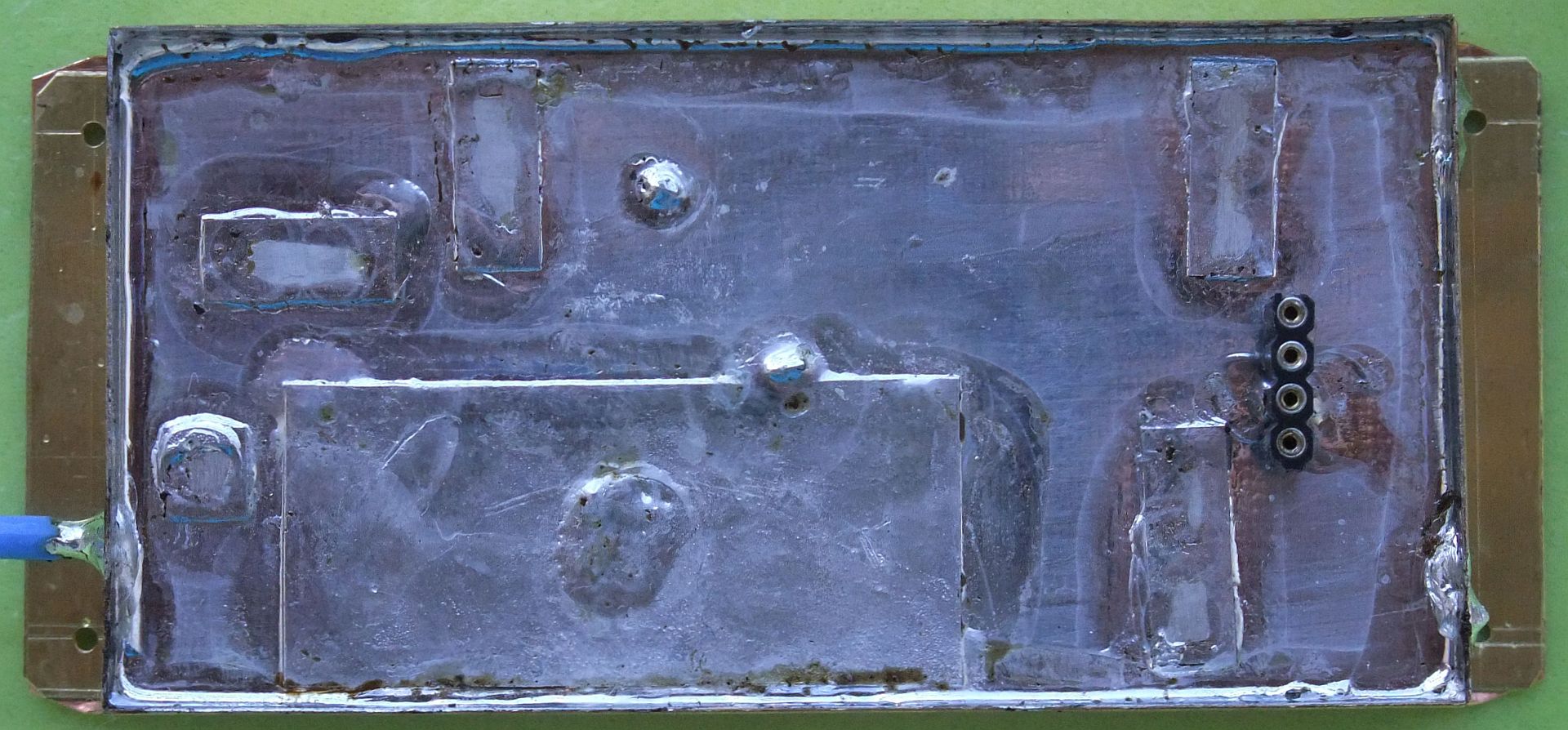
In the described transceivers, both RF boards, ZIF+PLL+modulator and front end, are soldered into frames made of 0.4mm-thick brass (Ms) sheet that is easy to soft solder. The completed module has the microstrip ground on the top and a cover made of 0.2mm-thick copper sheet (elastic) on the bottom, kept in place with four 2.2X6.5mm self-tapping screws. The same screws also hold the module on the bottom of the external case of the transceiver:
Radio-frequency connections are made with thin teflon-dielectric coax (RG188 or similar) on the narrow sides of the module. Supply and low-frequency connections are made through connectors installed on the ground side of the microstrip printed-circuit boards. Expensive and bulky feed-through capacitors are not used, although leakage through low-frequency connectors becomes noticeable above 3GHz.
The RF modules of the 1.2GHz version of the BPSK transceiver require the following parts made of thin brass (Ms) or copper (Cu) sheet. Thin tinned iron sheet (like used for coffee cans) can also be used except for the heatsink (head spreader) of the transmitter power device, where the high thermal conductivity of copper is very necessary:

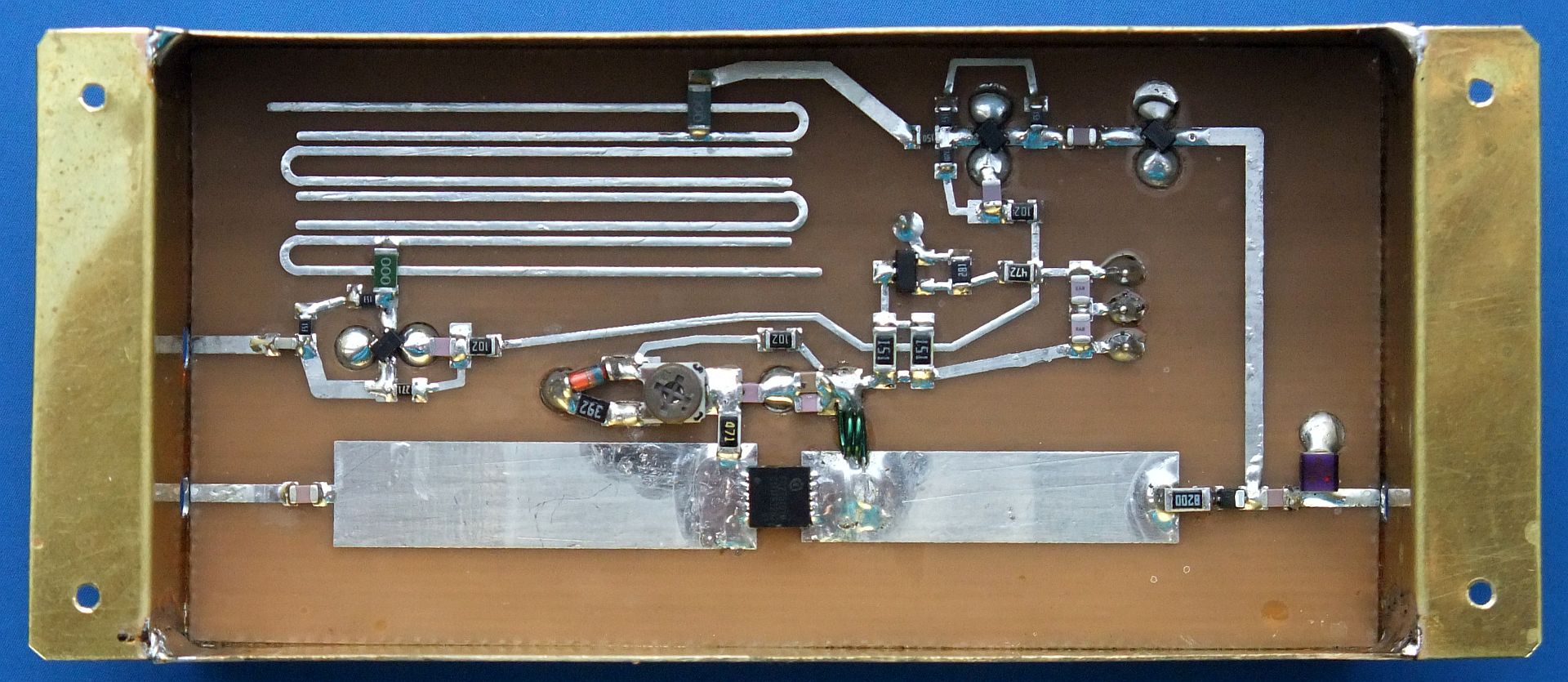
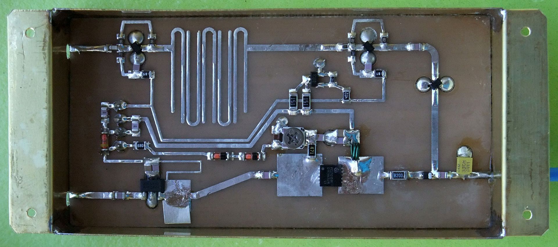
The RF-front-end module of the 1.2GHz version installed in the brass frame is shown on the following photo:
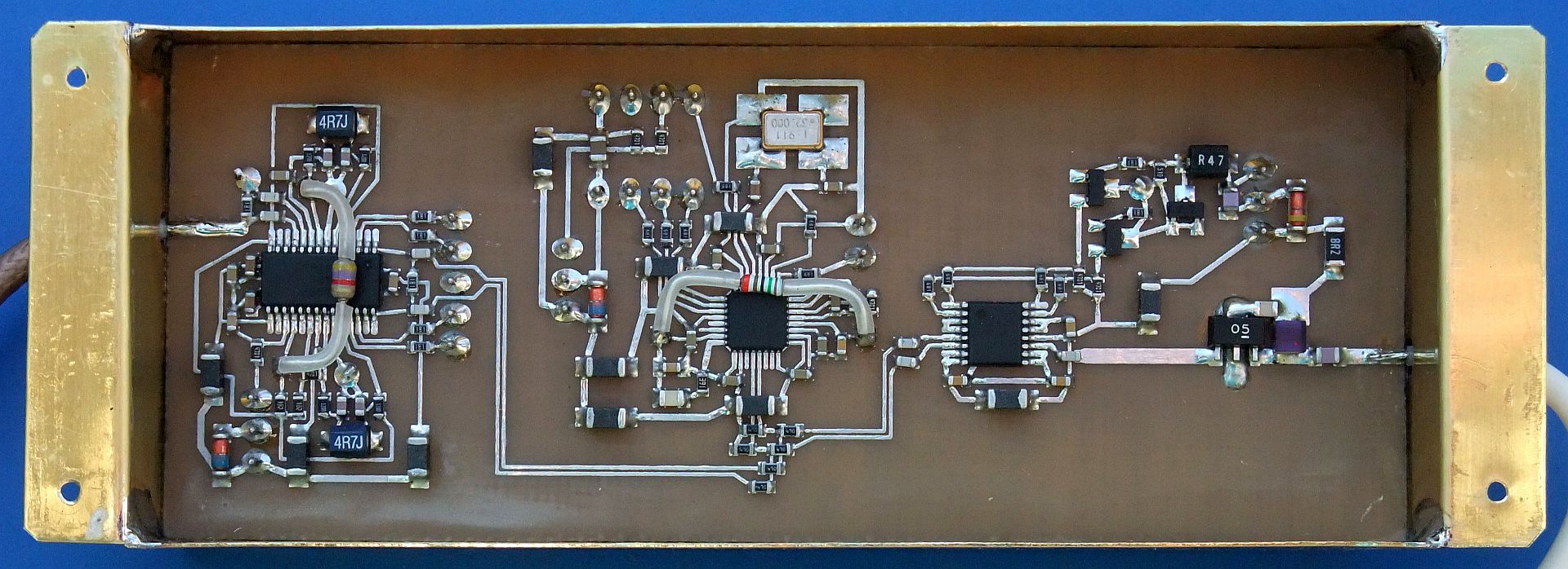
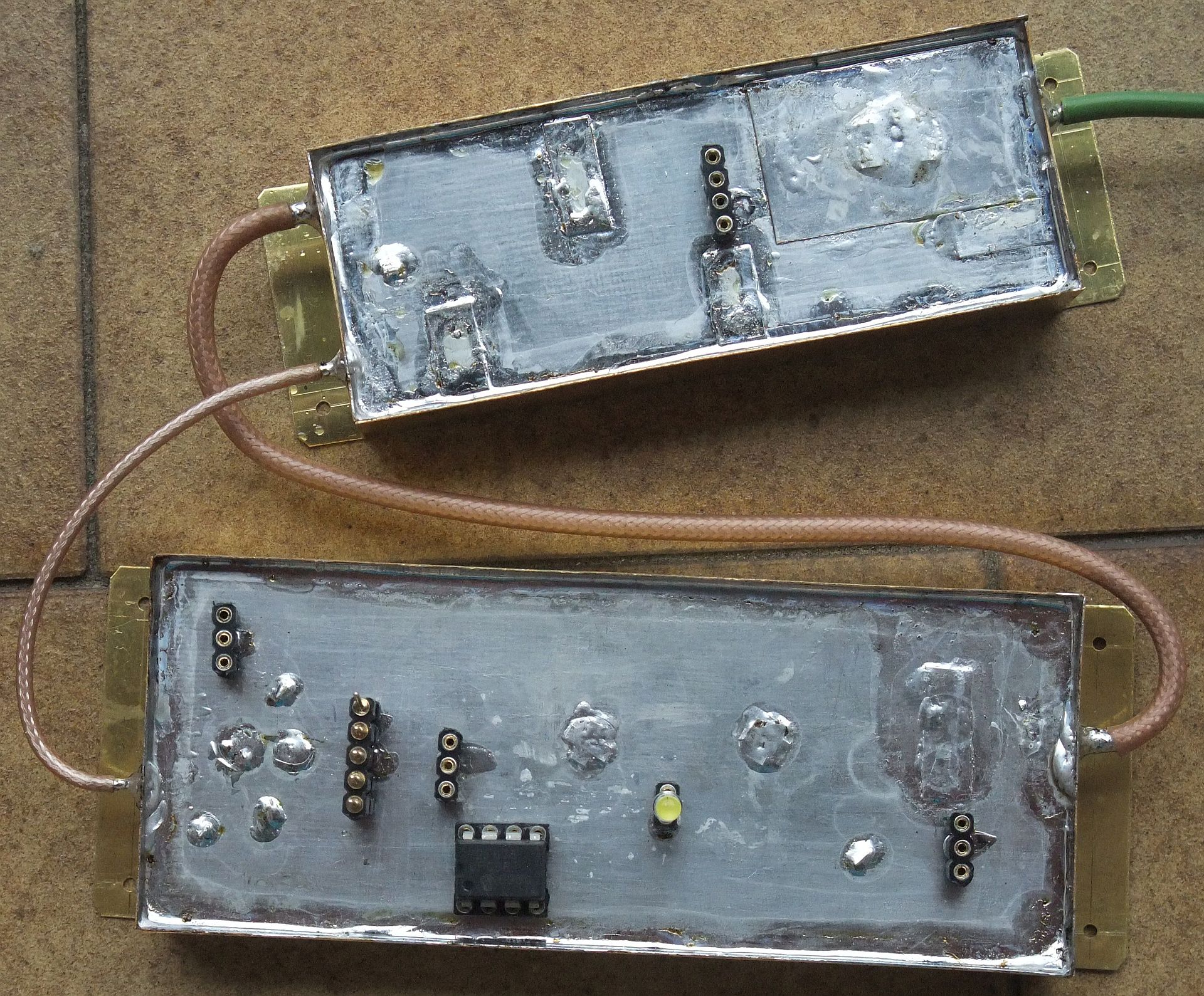
The ZIF+PLL+modulator module of the 1.2GHz or 2.3GHz version installed in the brass frame is shown on the following photo:
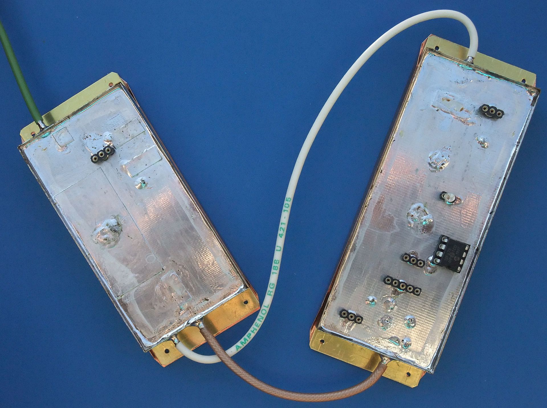
The RF modules of the 1.2GHz or 2.3GHz version are interconnected with thin teflon-dielectric coax of the following lengths: modulator to RF front end 19cm, RF front end to ZIF-RX 8cm and antenna to RF front end 7cm:
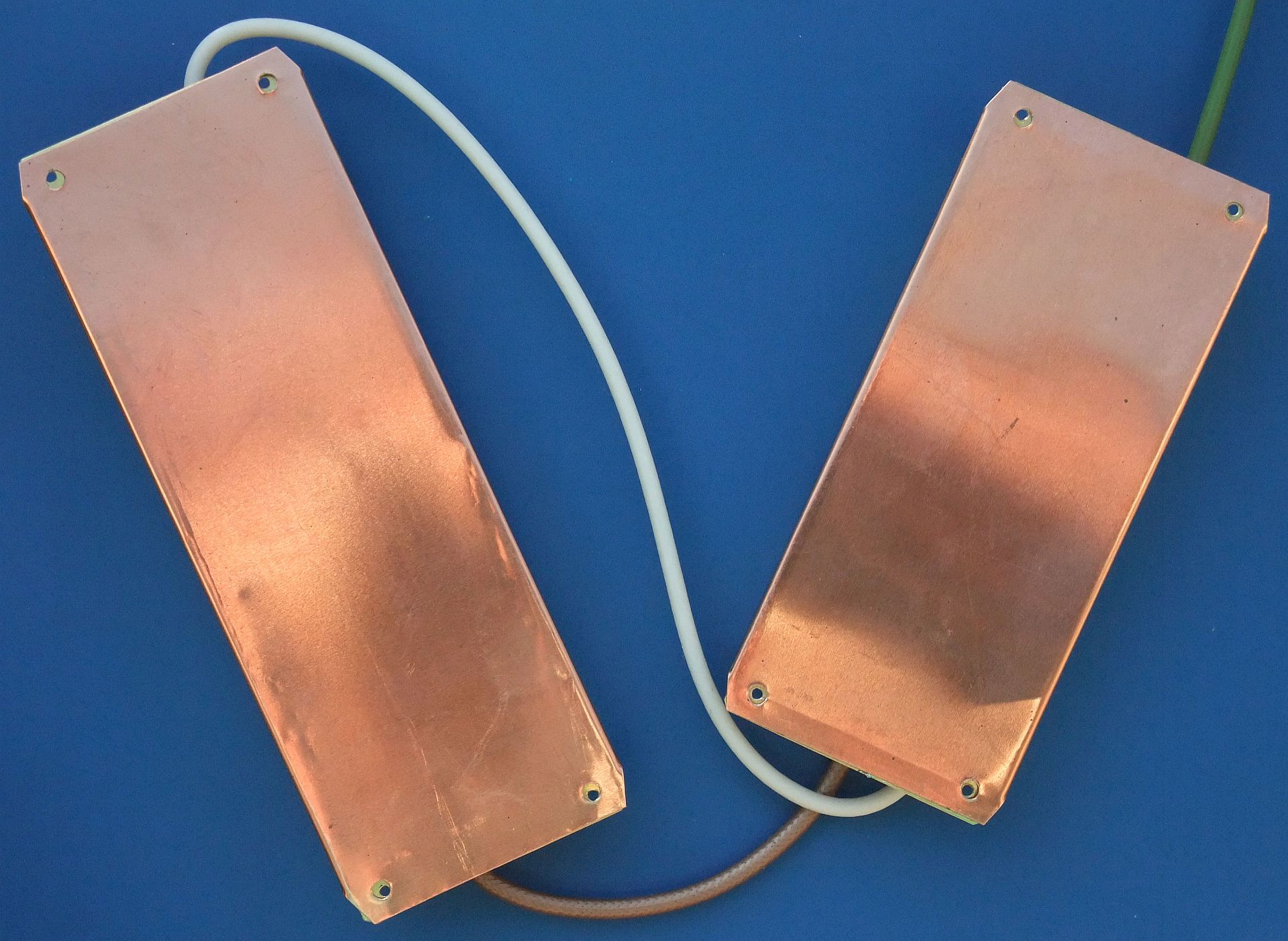
Both RF modules for 1.2GHz of 2.3GHz with copper covers in place are shown on the following photo:
The RF modules of the 2.3GHz version of the BPSK transceiver require the following parts made of thin brass (Ms) or copper (Cu) sheet. Thin tinned iron sheet (like used for coffee cans) can also be used except for the heatsink (head spreader) of the transmitter power device, where the high thermal conductivity of copper is very necessary:

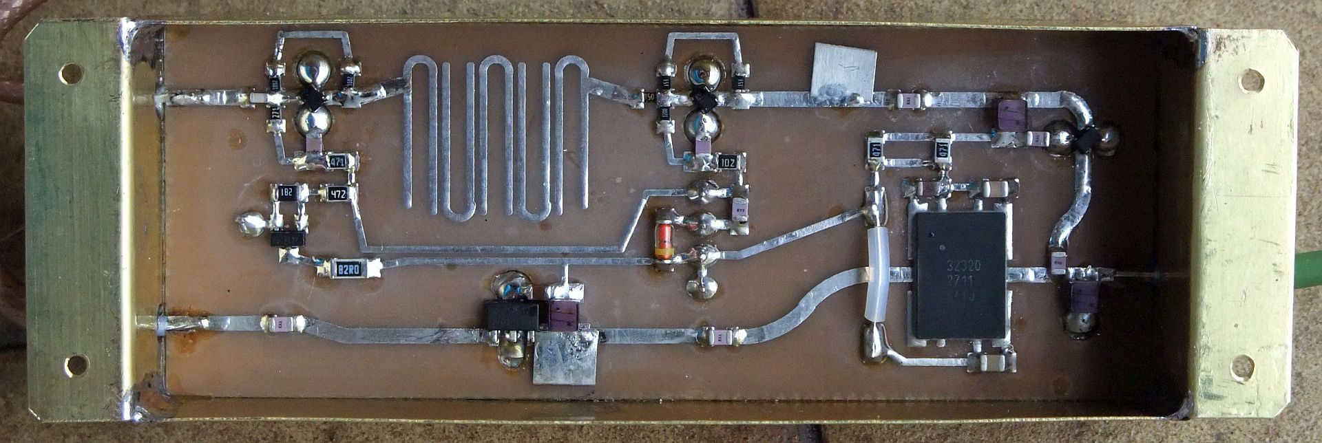
The RF-front-end module of the 2.3GHz version installed in the brass frame is shown on the following photo:
The top side of the same 2.3GHz RF front end is shown on the following photo:
The RF modules of the 3.4GHz version of the BPSK transceiver require the following parts made of thin brass (Ms) or copper (Cu) sheet. Thin tinned iron sheet (like used for coffee cans) can also be used except for the heatsink (head spreader) of the transmitter power device, where the high thermal conductivity of copper is very necessary:

The RF-front-end module of the 3.4GHz version installed in the brass frame is shown on the following photo:
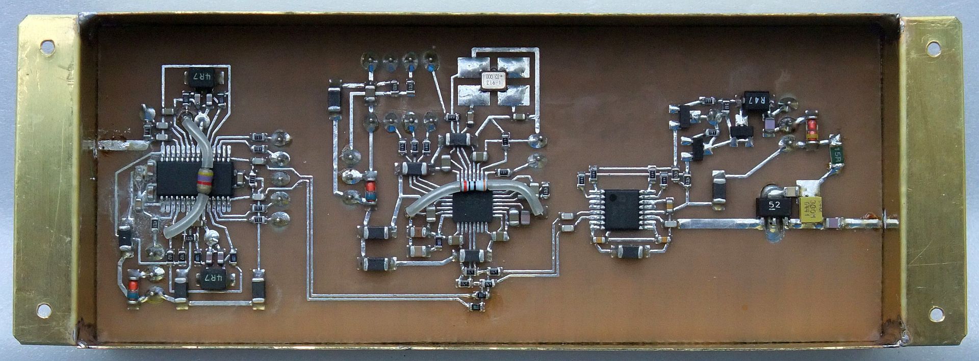
The ZIF+PLL+modulator module with the few components optimized for 3.4GHz is shown on the following photo installed in the brass frame:
The RF modules of the 3.4GHz version are interconnected with thin teflon-dielectric coax of the following lengths: modulator to RF front end 16cm, RF front end to ZIF-RX 7cm and antenna to RF front end 7cm:
(DESIGN) (COSTAS) (FRONTEND) (SUPPLY) (PCB) (SHIELD) (ASSEMBLY) (TEST) (HOME)