
(DESIGN)
(COSTAS)
(FRONTEND)
(SUPPLY)
(PCB)
(SHIELD)
(ASSEMBLY)
(TEST)
(HOME)
10Mbps BPSK ZIF transceivers for 1.2GHz, 2.3GHz and 3.4GHz
Matjaz Vidmar, S53MV
3. RF front ends
A RF front end should include a transmitting power amplifier (PA), a receiving low-noise amplifier (LNA), a receiving band-pass filter (BPF) and antenna switching between the transmitter and receiver. The transmitting power amplifier operates efficiently on a narrower frequency range than both the PLL synthesizer and the BPSK modulator. The receiving band-pass filter further limits the frequency band of the receiver to reduce interference to the wideband Zero-IF receiver. Different RF front ends are therefore required for different frequency bands.
The common ZIF, PLL and modulator were first tested in the 1.2GHz band together with the RF front end from 23cm BPSK RTX za 10Mbit/s (SLO - 23cm BPSK RTX for 10Mbit/s NBP packet-radio). The PD85004 power LDMOS transistor provided adequate gain (17dB) and output power (around +34dBm or 2.5W) with reasonable efficiency at the desired supply voltage around 12.5V. The PIN-diode antenna switch also performed flawlessly. The gain of the receiving LNA was found too low and the selectivity of the two-resonator band-pass filter was insufficient to suppress interference from cell-phone base stations in the 900MHz frequency range.
Designing a new RF front end a new transmitting power device was sought first. Unfortunately there are not many power transistors designed for linear operation in the 1.2GHz. Further most power transistors and amplifier chips are designed either for 5V operation (GaAs HEMT or HBT) or 28V operation (silicon LDMOS or still very expensive GaN HEMT). Devices for 13V operation similar to the PD85004 are hardly available.
Successful experiments were made with the PTFC270101M power LDMOS. The latter does not contain internal matching networks in its SON-10 SMD plastic package and is originally intended for operation in the 0.9GHz to 2.7GHz frequency band providing excellent gain at 10W output power and 28V supply voltage. At a supply voltage of only 12V it was found to provide about +36dBm (4W) of power at 1.2GHz, about +35dBm (3W) of power at 2.3GHz and with some difficult impedance matching +32dBm (1.5W) of power even at 3.4GHz. While still useful, the power gain at 12V is less than advertised for 28V operation.
Although solid-state antenna switches are available in different technologies, PIN diodes still provide the best results in the desired frequency and power range. The complexity and insertion loss of a PIN-diode antenna switch depends on the damage-power level of the LNA input. Besides high gain and low noise, new devices like the BFP840ESD bipolar transistor have a high input-damage level of +20dBm (100mW or at least ten times the input-damage level of a GaAs HEMT) thus simplifying the antenna switch.
In order to cover the noise of the AD8347 Zero-IF receiver, a LNA gain between 15dB and 20dB is required. Unfortunately, the gain of the AD8347 ZIF is not sufficient to drive the described digital Costas-loop demodulator with the EPM3032ATC44 inputs operated in their linear region. An additional, dual channel differential amplifier for the I, /I, Q and /Q quadrature signals would be the best solution. The latter may require its own AGC and increases the sensitivity to LO crosstalk and other interference.
A simpler solution is to increase the LNA gain to between 30dB and 35dB. This solution sacrifices about 15dB of the input RF dynamic range of the receiver. An efficient countermeasure is to insert a low-loss cavity filter like presented in Practical cavity filters for the frequency range 1GHz...4GHz in the antenna feed. With such a cavity filter the performance of the presented ZIF transceiver is comparable to earlier radios. In a difficult RF environment like a network node with many radios installed on a mountain top, high-performance antenna cavity filters are always necessary.
Three different RF front ends were developed and tested for the 1.2GHz, 2.3GHz and 3.4GHz frequency bands respectively. All three RF front ends are built a microstrip circuits on 0.6mm thick FR4 laminate and share many other design details. All three RF front ends are designed for stable operation regardless of the antenna impedance, in particular when using a narrow cavity filter.
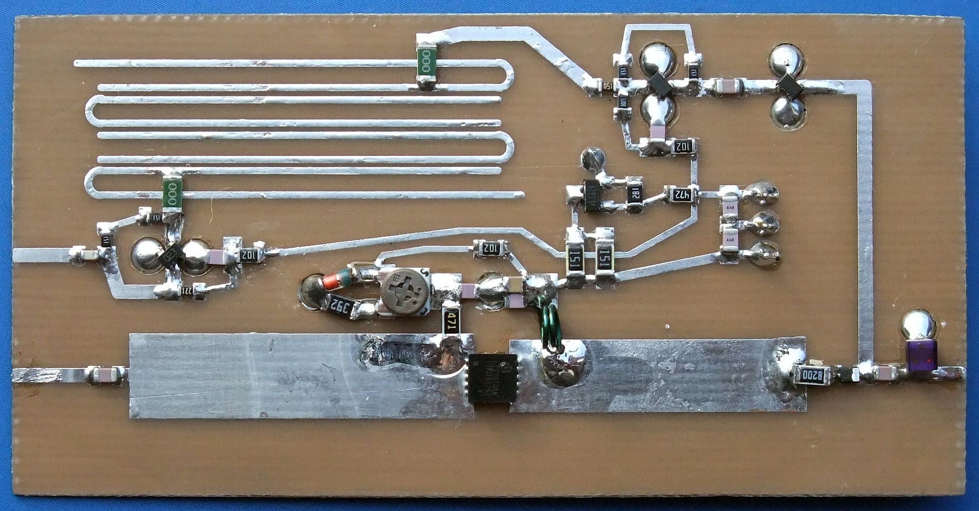
In the RF front end for 1.2GHz, a single PTFC270101M power LDMOS is sufficient to amplify the BPSK-modulator output to +36dBm (4W) on the antenna connector including PIN-switch losses. The PIN switch includes a series diode BAR63-03W for the transmitter and a shunt diode BAR81W for the receiver. The circuit with the FMMT493 transistor is required to speed up the antenna switching by discharging the capacitors on the +12VTX line. The LNA includes two stages with a total gain of about 33dB including the band-pass-filter losses. The latter has a bandwidth of about 200MHz and is specially designed (two jumpers 1206) to provide a notch for the 900MHz band:
The PTFC270101M operates in class AB. The quiescent current is set to about 100mA with the corresponding trimmer. The operating current may rise to above 700mA, therefore the 10nH drain choke is made as an air inductor with two turns of 0.45mm CuL wire on a 2.5mm internal diameter. Usually little if any tuning is required for the transmitter-output impedance match.
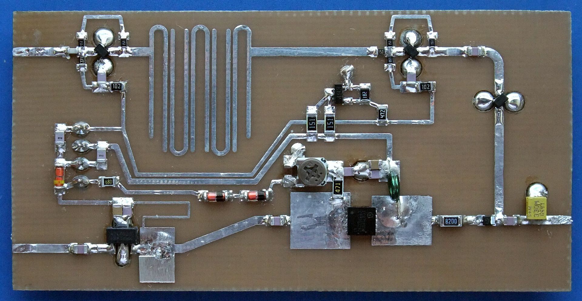
In the RF front end for 2.3GHz, a two stage amplifier with an ADL5320 MMIC and PTFC270101M power LDMOS is required to amplify the BPSK-modulator output to +35dBm (3W) on the antenna connector including PIN-switch losses. The PIN switch includes a series diode BAR63-03W for the transmitter and a shunt diode BAR81W for the receiver. The circuit with the FMMT493 transistor is required to speed up the antenna switching by discharging the capacitors on the +12VTX line. The LNA includes two stages with a total gain of about 33dB including the band-pass-filter losses. The latter has a bandwidth of about 400MHz:

The PTFC270101M operates in class AB. The quiescent current is set to about 100mA with the corresponding trimmer. The operating current may rise to above 600mA, therefore the 10nH drain choke is made as an air inductor with two turns of 0.45mm CuL wire on a 2.5mm internal diameter. Usually little if any tuning is required of the transmitter-interstage impedance match:
In the 3.4GHz band, the PTFC270101M provided little gain, required complex impedance-matching networks at both input and output and two additional driver stages to amplify the relatively low BPSK-modulator output. A simpler solution is the ALM32320 GaAs HEMT hybrid, providing +34dBm (2.5W) of output power when driven by an ALM5321 MMIC. Since the output impedance of the ALM32320 is reactive with the power off, a single shunt diode BAR81W and carefully chosen microstrip line lengths. The circuit with the FMMT493 transistor is required to speed up the antenna switching by discharging the capacitors on the +5VTX line. The LNA includes two stages with a total gain of about 33dB including the band-pass-filter losses. The latter has a bandwidth of about 500MHz:

The ALM32320 GaAs HEMT hybrid is best operated in class A to avoid dangerous voltage spikes on the +5VTX supply line. Usually little if any tuning is required of the transmitter-interstage impedance match. The MGA30789 MMIC provides less gain and output power than the ALM5321. On the other hand, the LNA always requires (+2dB gain!) a capacitive impedance-matching stub on its input:
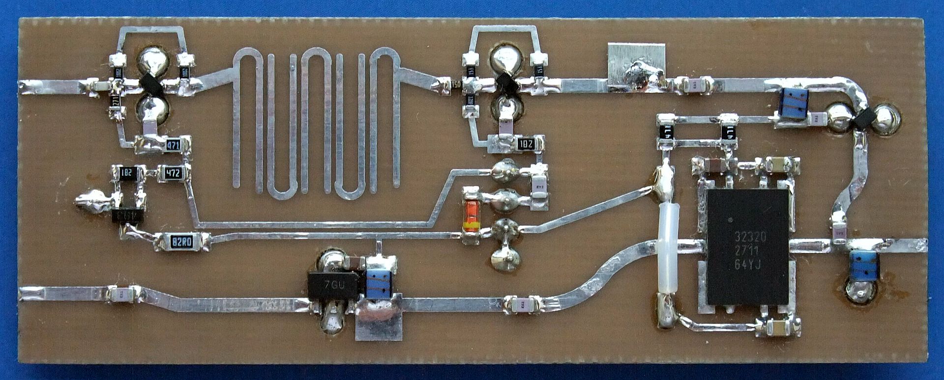
The RF front end for 3.4GHz is intentionally built on a narrower microstrip board to avoid parasitic resonances of the shielding. Unfortunately no 13V power devices are currently available for 3.4GHz. All available devices in the desired power range require a +5V supply like the obsolete ALM32320 GaAs HEMT hybrid, leading to poor power-supply efficiency. Finally, the 3.4GHz version of the presented BPSK transceiver should be considered experimental when compared to the operational 1.2GHz and 2.3GHz versions.
(DESIGN) (COSTAS) (FRONTEND) (SUPPLY) (PCB) (SHIELD) (ASSEMBLY) (TEST) (HOME)