Fig.1 - Extending the SA coverage with a harmonic mixer.
(VCO)
(SA)
(TG)
(HC)
(SN)
(MC)
(LCD)
(HOME)
Harmonic Converter for Spectrum Analyzers
Matjaz Vidmar, S53MV
1. Extending the frequency coverage of spectrum analyzers
RF spectrum analyzers are usually designed as scanning receivers with a high first intermediate frequency. If the first IF is set above the input frequency range, unwanted mixing products can be removed with a low-pass filter. Similar designs are therefore used also in other test equipment, like signal generators.
A high first IF implies that the circuits inside the test equipment should operate at relatively high frequencies. However, there are several technological constraints limiting the first IF to below about 5GHz. The most important constraint is probably the accumulation of phase noise of the oscillators used in the different up-conversions and down-conversions.
Practical spectrum analyzers therefore have the first IF in the range between 2GHz and 3GHz. For operation above 3GHz the input low-pass filter is replaced by a tunable (YIG) bandpass filter. Even without any input filtering, a spectrum analyzer is still able to provide useful information by carefully considering all mixing products with both the fundamental oscillator frequency and its harmonics.
For operation at very high frequencies (in the millimeter-wave range), commercial spectrum analyzers are usually supplied with external (waveguide) harmonic mixers, as shown on Fig.1. Of course the spectrum analyzer should provide both a LO output and an IF input to connect an external mixer. Some harmonic mixers may even require a bias adjustment to optimize the conversion efficiency at a particular harmonic.
Fig.1 - Extending the SA coverage with a harmonic mixer.
In a homemade spectrum analyzer one cannot probably afford an expensive YIG-tuned preselector. Although there may be differences in the conversion efficiencies of different mixers, harmonic mixing almost always provides useful results. The only remaining problem is the identification of the different mixing products when a tuned preselector is not available.
A very efficient solution is an additional harmonic converter, including a harmonic mixer and an adjustable local oscillator, as shown on Fig.2. The adjustable conversion oscillator allows an additional degree of freedom to shift the harmonic-mixer responses. The latter allows identification and convenient separation of the different mixer responses even without a tuned input preselector.
Fig.2 - Extending the SA coverage with a harmonic converter.
The same external (harmonic) converter can also be used to extend the frequency coverage of a tracking generator as shown on Fig.3. In fact the tracking generator itself is no longer needed, since the first LO output of the spectrum analyzer is used as the tracking generator. The additional (harmonic) converter is then used to translate the 2...3.7GHz band back to 0...1.7GHz, where the basic spectrum analyzer is receiving.
Fig.3 - Extending the tracking-generator coverage with a (harmonic) converter.
In the case of a typical spectrum analyzer with a 2GHz first IF this approach allows an additional coverage of 2...3.7GHz besides the usual range of 0...1.7GHz offered by conventional tracking generators. However, two constraints have to be met. First, the additional converter has to be tuned precisely to the SA first IF. Second, sufficient filtering has to be provided so that the converter oscillator does not enter into the SA IF. A separation buffer amplifier for the SA LO signal is required for the same purpose.
A simple, tunable harmonic converter for spectrum analyzers will be presented in this article. Although this converter was originally designed for the spectrum analyzer shown in [4] or [5], it will operate with any spectrum analyzer having the first IF between 2GHz and 3GHz. The detailed block diagram of the harmonic converter is shown on Fig.4.
Fig.4 - Harmonic converter detailed block diagram.
Besides a harmonic mixer the converter includes a tunable oscillator covering approximately the same frequency range as the VCO inside the spectrum analyzer (2.1...3.85GHz). The latter allows selecting the best mixing harmonic to obtain a spurious-free response and a good conversion efficiency at the same time. Of course the frequency coverage should include the SA first IF to allow the extension of the range of the tracking generator.
The (IF) output of the harmonic converter includes a wide-band amplifier and several low-pass filters. The amplifier is required to compensate for the high conversion loss of the harmonic mixer as well as poor noise figure of the following spectrum analyzer. Low-pass filtering has to be performed in several stages to remove all unwanted mixing products as well as to prevent the harmonics of the conversion oscillator from entering the basic spectrum analyzer.
Finally, the harmonic converter includes all required power supplies, since it is intended as a stand-alone unit. The VCO and output amplifier require a +8Vdc supply obtained with a 7808 regulator. A DC/DC converter with an additional stabilizer is used for the VCO tuning voltage 0...30V.
2. Harmonic mixer
The circuit diagram of the harmonic mixer is shown on Fig.5. In fact the harmonic mixer does not differ much from other mixers, like the first and second mixers in the spectrum analyzer shown in [4] or [5]. The dual schottky diode BAT14-099 produces useful harmonics up to at least 30GHz while driven with a large (+13dBm or 20mW) LO signal in the frequency range 2.1...3.85GHz.
Fig.5 - Harmonic mixer.
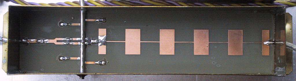
Since a flat response across the whole microwave frequency range is desired, particular attention has to be made to suppress any parasitic resonances of the circuit. The input signal is therefore coupled using very small 0402 SMD capacitors. Since the width of a single capacitor is 0.5mm, three such capacitors are installed in parallel to match the 1.5mm width of the 50ohm microstrip line.
Unwanted resonances of the balun made from UT-085 semirigid cable are suppressed by four 68ohm SMD resistors. The 10ohm and 22ohm resistors are also used to suppress circuit resonances. Finally, the whole shielded module requires a piece of microwave absorber (antistatic foam) under the cover to suppress cavity resonances.
The harmonic mixer does not include any attenuator on the input. Since it is difficult to build good attenuators for frequencies above 10GHz with conventional SMD resistors, it is recommended that external SMA attenuators are used when required. The SMA connectors themselves limit the frequency range of the harmonic mixer to about 26GHz. Although there is no input filter, waveguide transitions were found to be excellent high-pass filters when required.
3. Wide-band VCO
The design of a suitable wide-band VCO was already shown in [1], [2] or [3]. The circuit diagram on Fig.6 has just a small modification. A 10uF capacitor is added to the tuning voltage line for additional filtering, since inside the harmonic converter the VCO frequency is only set manually wih a precision Helipot potentiometer.
Fig.6 - Wide-band VCO.
The main output of the VCO (+13dBm) drives the harmonic mixer directly. The auxiliary output (about -5dBm) is made available on the back panel. The latter may be used to check the conversion frequency with a counter or as a 2...3.85GHz signal source for other purposes.
For operation with the spectrum analyzer described in [4] or [5] or other spectrum analyzers with the first IF around 2GHz, BB833 varactors should be used in the VCO to allow a frequency coverage from about 2GHz to about 3.85GHz. For spectrum analyzers with the first IF above 2.5GHz, BB857 varactors are recommended (VCO range 2.4GHz to 4.6GHz).
4. Output amplifier
The circuit diagram of the output amplifier is shown on Fig.7. The amplifier is designed around an INA10386 MMIC that provides a flat gain of more than 20dB and a noise figure better than 4dB across the whole frequency range up to 1.75GHz. The INA10386 provides just the correct amount of gain to compensate for the mixer conversion loss and SA noise figure.
Fig.7 - Output amplifier.
The output amplifier is necessarily installed in its own shielded enclosure, since unwanted signal filtering is very critical. Besides the low-pass filter inside the harmonic mixer module (cutoff about 1.75GHz), two additional low-pass filters with cutoff frequencies of about 2.8GHz are installed before and after the INA10386 amplifier. To suppress higher-order responses of the microstrip circuits as well as enclosure cavity resonances, microwave absorber foam is also needed under the cover of the amplifier module.
The INA10386 MMIC requires DC decoupling capacitors on both the input and output. Since the harmonic converter is usually used at relatively wide SA resolution bandwidths (100kHz or more), the IF range can be limited to 100kHz on the lower end. Even in the latter case finding suitable coupling capacitors is not simple. The best results were found with a parallel connection of a low-loss, 100pF NP0 0805 size capacitor that is soldered on the PCB first. Then a lossy 100nF (Z5U ceramic) and larger (1206) capacitor is soldered across the smaller 100pF capacitor.
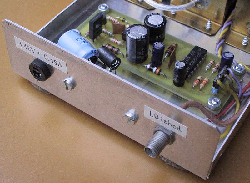
5. Power supply
Like the spectrum analyzer described in [4] or [5] or the companion tracking generator described in [6], the harmonic converter requires an unstabilized +12Vdc supply. The latter is stabilized to +8V with a 7808 regulator to supply the VCO and output amplifier. The 7808 regulator is wired exactly in the same way as in the spectrum analyzer or tracking generator. The harmonic converter usually remains on all of the time to minimize frequency drifts, so a turn-on switch is usually not required.
The BB833 (or BB857) varactors inside the wide-band VCO require much higher tuning voltages up to +30V. Further, the tuning voltage has to be well stabilized and filtered, to avoid frequency drifts and excessive phase noise. Both unwanted effects are further multiplied by the order of the harmonic inside a harmonic converter!
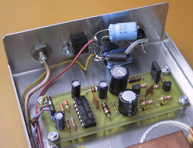
The tuning voltage supply is shown on Fig.8. The circuit includes a flyback DC/DC converter with the transistors BC308 and BD139. The rough voltage regulation provided by the two 18V zener diodes and BC548 feedback transistor is far from being sufficient for a tuning voltage. The resulting +37V is further stabilized down to +30V with a uA723 precision regulator. Due to the low current drain at +30V, no external transistors are required around the uA723. However, the uA723 still requires some feedback resistors to set the output voltage, over-current protection and a capacitor for frequency compensation.
Fig.8 - Stabilized DC/DC converter.
The actual VCO tuning voltage is obtained through a precision 50kohm Helipot potentiometer from the well-regulated +30V supply. The potentiometer is installed on the front panel and is equipped with a revolution-counting dial knob. Since there is no tuning-voltage linearizer, the frequency scale is quite nonlinear. The latter may even be an advantage in a harmonic converter, where fine frequency adjustments are usually required at the upper end of the frequency coverage while using high-order harmonic mixing at input frequencies above 10GHz.
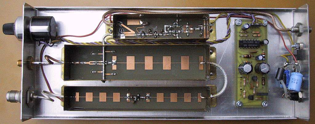
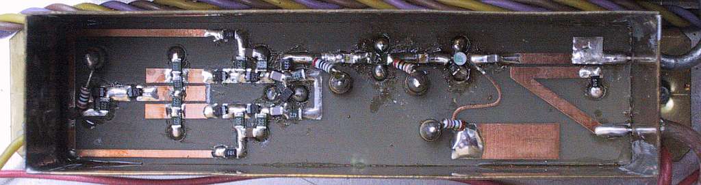
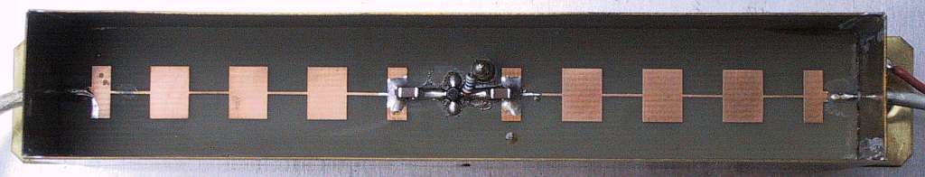
6. Construction tips
With the exception of the DC/DC converter, the harmonic converter only includes microstrip circuit boards. The harmonic mixer and output amplifier boards are shown on Fig.9 while the wide-band VCO has already been described in [1], [2] or [3]. All microstrip boards are etched on 0.8mm thick, double-sided FR4 glassfiber-epoxy laminate. The DC/DC converter is built on a single-sided board as shown on Fig.10, etched on 1.6mm thick FR4 laminate.
Fig.9 - Microstrip circuit boards (150dpi).
Fig.10 - DC/DC converter PCB (30X80, 150dpi).
All three microstrip boards are installed in shielding boxes made from 0.5mm thick brass sheet just like the modules of the spectrum analyzer [4] or [5] or companion tracking generator [6]. All three brass boxes require a microwave absorber (antistatic foam) under their covers to suppress cavity resonances.
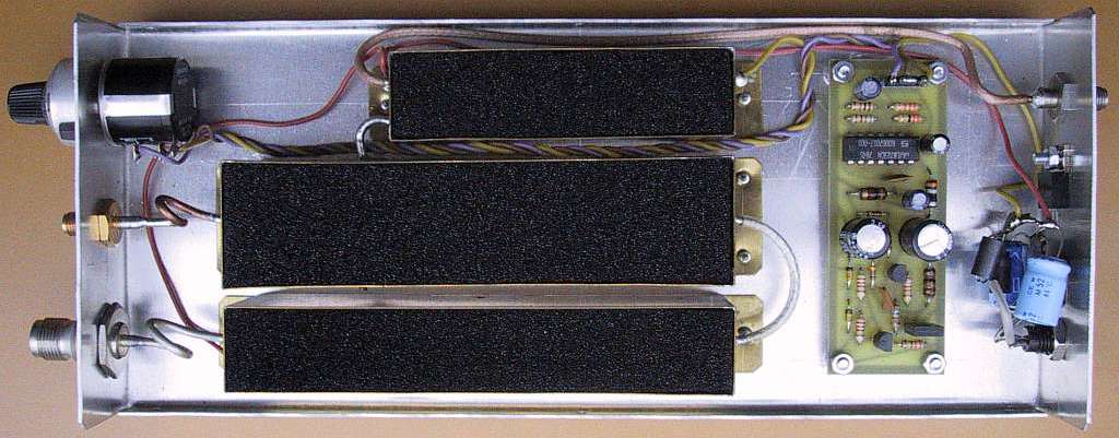
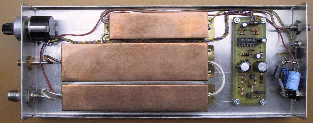
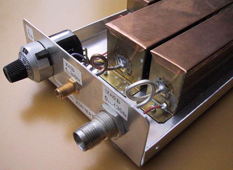
The harmonic converter module location is shown on Fig.11. The harmonic converter has the same depth (240mm) as the spectrum analyzer [4] or [5]. The width is 100mm while the heigth is only 32mm, since all modules are located in a single plane. The bottom of the box is simply a piece of 1mm thick aluminum sheet, bent in the form of an "U". The cover is a similar "U" made from 0.6mm thick aluminum sheet.
Fig.11 - Harmonic-converter module location.
The 7808 regulator is bolted to the back plate for heatsinking purposes. The two 470uF electrolytic capacitors, VK200 RF choke and 1N5401 diode are simply soldered between the +12V supply connector and the leads of the 7808 regulator. The overall current drain amounts to about 150mA.
7. Alignment and checkout
A harmonic converter is a much simpler piece of test equipment when compared to a spectrum analyzer or companion tracking generator. The described harmonic converter has no tuning points. Of course, the correct operation of the power supply including the DC/DC converter should be checked first.
The most demanding module is certainly the wide-band VCO. The latter should be checked for the frequency coverage as well as output-signal level. The latter should not drop below +10dBm on any frequency. Of course, if the spectrum analyzer published in [4] or [5] is being built at the same time, it makes sense to install the better VCO inside the spectrum analyzer and use the remaining VCO for the harmonic converter.
The spectrum analyzer should be sensitive enough to display the noise of the harmonic-converter output amplifier even with an input attenuator setting of 10dB. This corresponds to a spectrum-analyzer noise figure of about 20dB (without the input attenuator) that is a typical value for most spectrum analyzers.
Finally the first LO output from the spectrum analyzer is connected to the harmonic-converter. Additional attenuators may be required to bring the input signal level of the latter to about -10dBm. When the harmonic converter is tuned to the exact first IF of the spectrum analyzer, the setup can be used as a tracking generator.
Original full-size drawings

References:
[1] Matjaz Vidmar: "Wideband & Low-Noise Microwave VCO", pages 28.1-28.16/Skriptum der Vortraege, 43. Weinheimer UKW Tagung, 19.-20. September 1998.
[2] Matjaz Vidmar: "Rauscharmer, breitbandiger Mikrowellen VCO", pages 26-35/4-98, AMSAT-DL Journal.
[3] Matjaz Vidmar: "Wideband & Low-Noise Microwave VCO", pages 210-225/4-98, VHF-Communications.
[4] Matjaz Vidmar: "Spectrum analyser 0...1750MHz", pages 2-30/1-99, VHF-Communications.
[5] Matjaz Vidmar: "Spektrum-Analyzer von 0 bis 1750MHz, Teil 1: Aufbau der Baugruppen", pages 18-30/4-99, "Spektrum-Analyzer von 0 bis 1750MHz, Teil 2: Anzeigebaugruppen und Abgleich", pages 18-29/1-00, AMSAT-DL Journal.
[6] Matjaz Vidmar: "Tracking Generator for the Spectrum Analyser 100kHz to 1750MHz", pages 66-79/2-99, VHF-Communications.
* * * * *