(VCO)
(SA)
(TG)
(HC)
(SN)
(MC)
(LCD)
(HOME)
LCD Oscilloscope for Spectrum Analyzers
Matjaz Vidmar, S53MV
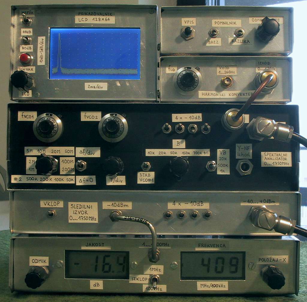
1. Spectrum-analyzer project 2007 update
Since the development of the wide-band VCO almost 10 years ago, the whole spectrum-analyzer project with all related accessories: tracking generator, harmonic converter, storage-normalizer, marker counter and accessories developed by other experimenters (Darko S57UUD) have been published in many different places: magazines "VHF-Communications", "AMSAT-DL Journal", "CQ ZRS" and the book "Beacon 99" (project Phare, http://www.s53m.com/). It is reasonably believed that the the project has been successfully reproduced in hundreds of units.
Since the spectrum-analyzer project is still very interesting for many radio amateurs and other radio and electronic experimenters, I decided to republish my original articles in English on my personal web page. Unlike printed magazines, the web allows to publish many color pictures of all interesting details of the project in addition to PDF, PCB and software files. Last but not least, updates to the project are really simple on the web.
In this article a simple and inexpensive LCD oscilloscope to be used as a display for the spectrum analyzer will be presented. Although a small LCD screen is unable replace a good analog oscilloscope, a LCD may be very useful in field measurements under strong daylight conditions, for battery operation or simply when the available oscilloscope is required for a different measurement at the same time.
Before describing the LCD oscilloscope, some necessary updates to the spectrum-analyzer project will be presented. As expected and also according to the feedback, the most difficult part to reproduce is the wide-band VCO. This difficulty is in part due to component tolerances and in part due to assembly (soldering) tolerances. In particular, the BB833 varactor diodes were found to have rather wide manufacturing tolerances both in the capacitance range and in the series (loss) resistance affecting the Q of the varactor.
As already explained in the VCO article, two different printed-circuit boards are proposed for the wide-band VCO. Starting with unknown components, one should always assemble the "narrow-stripe" wide-band VCO first (PCB#1). The "wide-stripe" PCB#2 should only be used if the frequency coverage obtained with PCB#1 is insufficient.
If output power of the wide-band VCO drops in the middle of its frequency range between 2.5GHz and 3GHz or the VCO simply stops oscillating at all in this frequency range, excessive losses in the BB833 varactors are suspected. Besides poor varactor Q (try getting better BB833 varactors from a different source), the interdigital feedback filter may be misaligned due to soldering tolerances. In the latter case, a rather simple solution is to try to trim the length of the open end of the central finger of the interdigital filter.
Although the wide-band VCO design was also published in a well-respected and widely-known professional magazine "Microwave Journal" already back in 1999 [1], it took several years for the professionals to fully understand the operation and capabilities of this VCO design. Multiple-resonator-multiple-varactor microwave VCO modules only became available recently on the professional market. Finally, there is a valid and inexpensive alternative to the YIG oscillator! Of course, these inexpensive commercial VCO modules can be used in place of the described wide-band VCO.
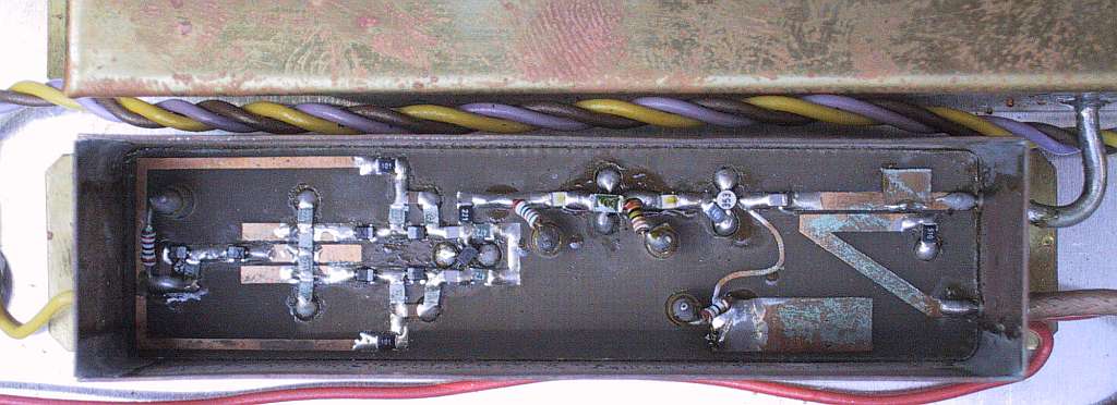
After using the described spectrum analyzer and all related accessories for many years, some long-term effects were noted as well. The worst seems to be the corrosion caused by outgassing chemicals from the antistatic foam used as a microwave absorber in high-frequency shielded modules. A higher conductivity foam makes a better microwave absorber, but unfortunately more chemicals cause more corrosion as well! Fortunately, the microstrip circuits of the spectrum analyzer continue to work correctly with little if any degradation, although they really look ugly...
A less-frequent problem is a long-term failure of ATF35176 or similar HEMT devices. If the voltage between drain and source is kept too high, the drain current slowly decays. This decay may be very slow, just a few percent per week, but it is cumulative, irreversible and continues down to zero leading to a total failure of the circuit!
In this project, HEMTs are used in the buffer stages of wide-band VCOs and in the buffer amplifiers inside the tracking generator. The described failure can be detected as a rise of the drain voltage. If the drain voltage rises above +3V...+3.5V, the decay will speed up and the HEMT will have to be replaced soon, possibly with better devices.
Some electronic parts became obsolete or hard to get. The most difficult seems to be the INA10386 MMIC amplifier that has no direct replacement. Worst of all, defective factory rejects are shipped for some obsolete parts, like the uA723 voltage regulator. Some uA723 regulators have a very noisy voltage reference with very large 1/f "popcorn" noise. The latter may be large enough to disturb even large-signal circuits like the video amplifier inside the spectrum analyzer.
Besides getting better uA723 regulators, there is a simple solution to this problem. The internal 7V voltage reference, available on pin 6, should be filtered before use. If the latter is fed through a resistor to pin 5 (non-inverting input), then a single electrolytic capacitor from pin 5 to ground (pin 7) solves the problem.
2. LCD oscilloscope for spectrum analyzers
LCD modules are probably the most popular displays today, ranging from simple numerical displays with few single-color digits to large, graphical, high-resolution, full-color computer monitors. A medium-resolution, single-color graphical LCD module is required in an oscilloscope display for a spectrum analyzer. Of course, a simple solution was sought for the described spectrum-analyzer project.
Medium-resolution graphical LCD modules may have different interfaces. The simplest LCD modules have no built-in controller. These modules only have shift registers associated with the columns and rows of the display. The user has to provide a continuous data flow to refresh and multiplex the display content. This requires a powerful microprocessor with lots of memory or in other words a complicated circuit with many chips.
LCD modules with a built-in controller providing the refresh and multiplex of the display are much simpler to use. The most popular alphanumeric controller is certainly the Hitachi HD44780, that even has some very limited graphical capabilities. Older graphical LCD modules use the Toshiba T6963 controller with an external 8kbyte RAM (usually 6264). These modules also require a negative-voltage supply for the LCD and a high-voltage AC source for the electro-luminescent backlight.
Recent graphical LCD modules use the Samsung KS0107 and KS0108 chips. The KS0107 is the clock generator, scans 64 rows and may drive multiple KS0108 chips. The KS0108 drives the columns and includes storage for up to 64x64 dots. The microprocessor simply writes into the RAM inside the KS0108 chips. These modules usually include one or two 7660 chips to generate the required negative Vee LCD supply of -5V or -10V on-board the LCD module. Finally LEDs are used for the backlight so that the module can be operated from a single +5V supply.
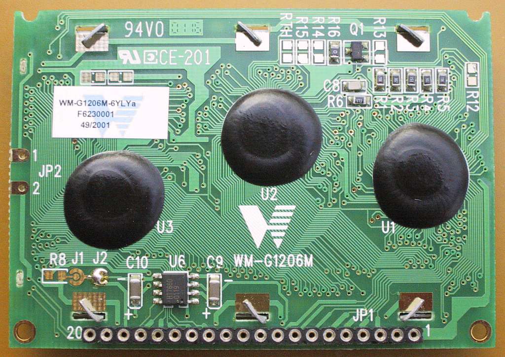
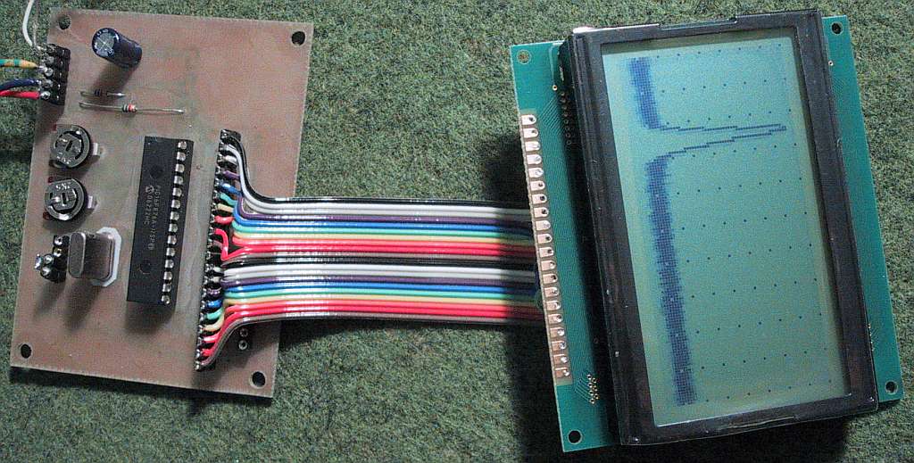
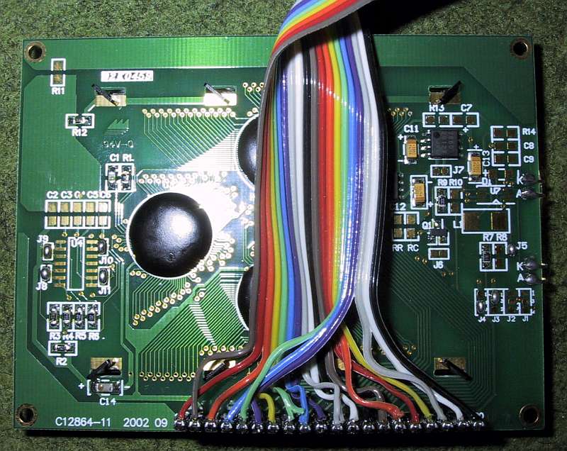
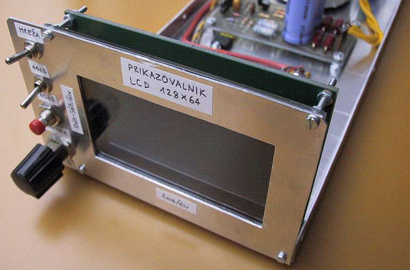
A 128x64 graphical LCD module is used in the described LCD oscilloscope. This module includes one KS0107 and two KS0108 chips. All three controller chips are usually bonded directly to the printed-circuit board and covered with drops of black resin.
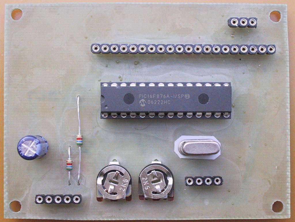
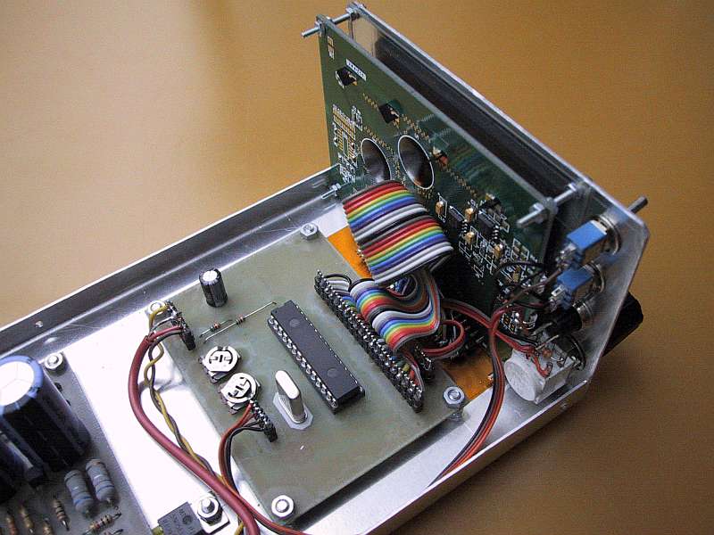
The LCD oscilloscope is built around a PIC 16F876A microcontroller. The latter includes an A/D converter and steers the graphical LCD module directly. The circuit diagram of the LCD oscilloscope is shown on Fig.1.
Fig.1 - LCD oscilloscope for spectrum analyzers.
The LCD oscilloscope requires two signals from the spectrum analyzer: the analog video (including blanking) and the trigger. Due to the limited resolution of the LCD, the analog signal is oversampled. Each column on the LCD is computed from eight consecutive samples and the last sample from the previous column. The A/D sampling rate is set so that the whole sweep (128 columns or 1024 samples) corresponds to about 20ms or in other words the fastest rate of the described spectrum analyzer.
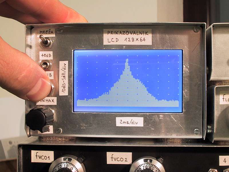
Additional inputs to the microcontroller are provided for two switches and one pushbutton. One switch is used to turn on the grid while the other selects a 80dB (4V) or 40dB (2V) full-scale range. The scale is adjusted by two trimmers defining the reference voltages of the A/D converter. The pushbutton activates a MIN/MAX memory that is very useful when observing wide-deviation slow FM signals or infrequent pulsed signals on the spectrum analyzer.
All outputs of the PIC 16F876A have series 1.8kohm damping resistors to reduce the amount of radio interference radiated by the microcontroller. The same resistors are also used to operate the data bus to the LCD module bidirectionally, simplifying the programming of the PIC 16F876A. In particular, the RC0-7 pins are always programmed as outputs. In order to read the status of the KS0108 controllers, the DB7 line is also fed back to the RB1 input.
The display-refresh rate is limited by three factors: the A/D-conversion speed, the PIC computing power and the wait cycles required by the KS0108 controllers. In the described LCD oscilloscope, all three factors are of the same order of magnitude limiting the refresh rate to about 35Hz...40Hz and thus providing a live picture of the input signal. A minimum clock frequency of 20MHz is required for the PIC 16F876A for this purpose.
A 24MHz clock for the 16F876A was therefore selected to allow the spectrum-analyzer sweep time to remain at 20ms at all times with some safety margin. This is consistent with the resolution of the display (128 columns) and available filter bandwidths and spans of the spectrum analyzer. Slower signals can be observed with the MIN/MAX function, using 256 bytes of the internal RAM inside the 16F876A. The minima and maxima are simply accumulated as long as the MINMAX pushbutton is kept depressed.
The same 256 bytes of internal RAM are also used for 128 minima and 128 maxima storage during normal operation without the MIN/MAX function. The A/D routine runs under interrupts triggered by an internal timer inside the PIC 16F876A. The main program is an endless loop computing and refreshing the LCD content from the intermediate storage. Yet another interrupt is used for the trigger function.
The described LCD oscilloscope is fully compatible with all described accessories: tracking generator, storage-normalizer and marker counter. The 40dB scale is in fact intended for reflection measurements with the tracking generator and an additional, external directional coupler. The oversampling of the video signal allows a proper display even of the 455kHz marker.
The LCD oscilloscope includes its own +5V regulator (78L05). The latter also provides power to the backlight LEDs through two 10ohm current-limiting resistors. Current-limiting resistors and other protection components are also provided on all inputs to the module.
3. 230V mains power supply
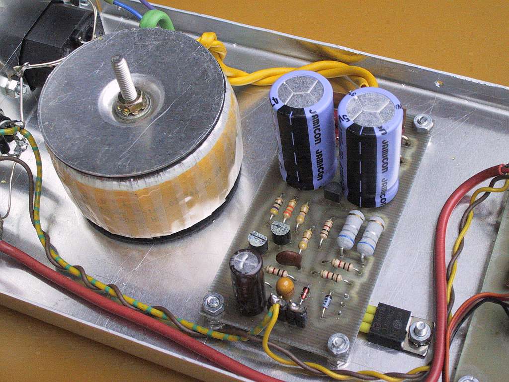
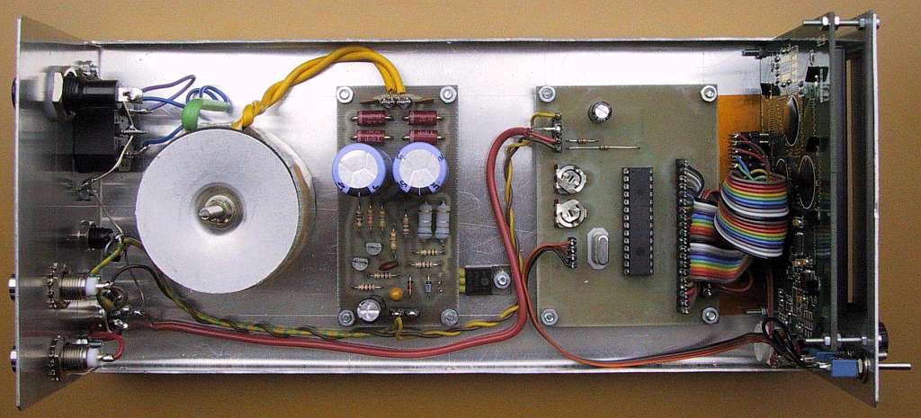
Since the described LCD oscilloscope is small and simple, the remaining space behind the LCD module is used for a 230Vac mains power supply, providing 12V for the LCD oscilloscope, spectrum analyzer and all accessories. The circuit diagram of the power supply is shown on Fig.2.
Fig.2 - 230V mains power supply.
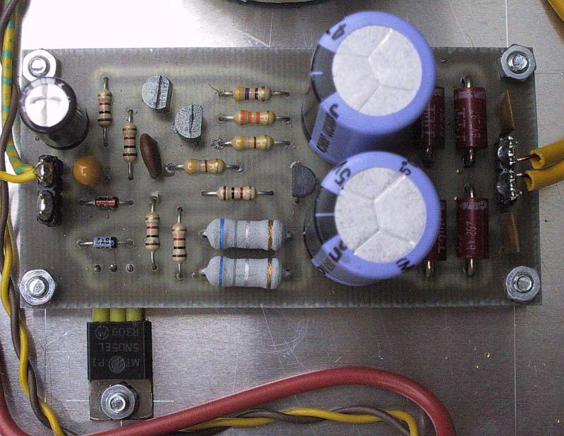
The discrete-component regulator has many advantages over integrated circuits: very low drop-out voltage, grounded heatsink of the power device and last but not least, no additional protection diodes are required in the case of (parallel) 12V-battery operation! Since the spectrum analyzer is sensitive to low-frequency magnetic fields, it is imperative to use a toroidal-core transformer in the power supply.
4. Assembly of the LCD oscilloscope
The first thing to do is to check the availability and size of suitable LCD modules with the KS0107/KS0108 controller chips. Do not forget to check the presence of the 7660 Vee generator as well as the type of backlight available. Last but not least, check the connections of the available LCD module!
The printed-circuit board was developed for Wintek LCD modules. Other manufacturers may use a different pin-out requiring to swap some wires. In particular, the Vdd (+5V) and Vss (GND) connections may be swapped! CS1 and CS2 may be active-low or active-high, since each KS0108 actually has three such inputs (two inverted) and just one is brought out to the connector.
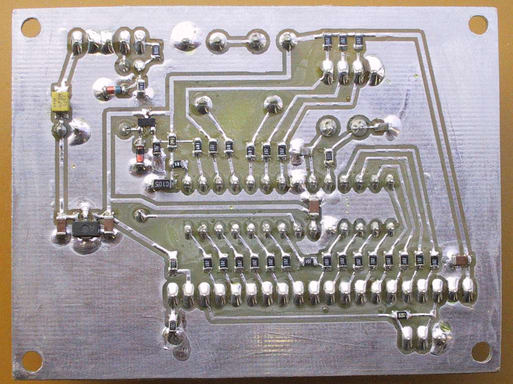
The LCD oscilloscope is built on two printed-circuit boards as shown on Fig.3. The PIC 16F876A and associated components are installed on a single-sided printed-circuit board with the dimensions of 80mmX60mm. The power-supply regulator is built on a single-sided printed-circuit board with the dimensions of 80mmX40mm. Both circuit boards are etched on 1.6mm-thick glassfiber-epoxy laminate FR4.
Fig.3 - Printed-circuit boards (150dpi).
The LCD oscilloscope has the same depth (240mm) as the spectrum analyzer [2] or [3]. The width is 110mm while the height is set to 70mm considering the size of the available LCD module. All modules are located in a single plane. The bottom of the box is simply a piece of 1mm thick aluminum sheet, bent in the form of an "U". The cover is a similar "U" made from 0.6mm thick aluminum sheet.
Besides the DIN connector, two additional BNC connectors for the video+blanking and trigger signals are provided on the back panel to connect an additional, high-quality, analog oscilloscope. Although the LCD oscilloscope is protected from over-voltages on all inputs even in the power-down state, the LCD oscilloscope should be powered at all times to avoid loading the outputs of the spectrum analyzer.
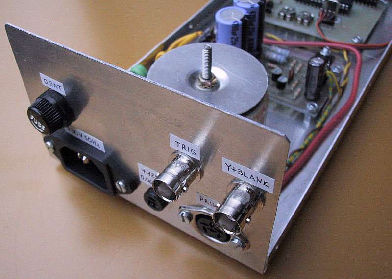
Besides the LCD module, two switches (grid on/off and scale 40dB/80dB), the MINMAX pushbutton and the LCD-contrast potentiometer are located on the front panel. The latter could be omitted, since LCD modules from many different manufacturers were found to operate best at the maximum voltage. This means that the Vo input is simply tied to the Vee output through the 82kohm resistor on the printed-circuit board and no additional potentiometer is required.
The described LCD oscilloscope will display correctly input voltages between about +0.7V and +5.5V due to the emitter follower in front of the A/D converter. Therefore the trimmers inside the video amplifier of the spectrum analyzer [2] or [3] may need to be readjusted first, using a reliable analog oscilloscope. The trimmers inside the storage-normalizer and marker counter may need some minor readjustments as well.
Finally, the 80dB scale of the described LCD oscilloscope can be adjusted with the two trimmers providing the reference voltages to the A/D converter. Please note that the operation of the LCD oscilloscope is slightly different between the 80dB mode and the 40dB mode. In the 80dB mode, the trace is always visible and saturates on the bottom or top of screen. In the 40dB mode, the trace runs out of the screen and only the central part of the original 80dB scale is displayed.
Datasheets, PCB files & PIC software

References:
[1] Matjaz Vidmar: "A Wideband, Varactor-tuned Microstrip VCO", pages 80-86/6-99, Microwave Journal.
[2] Matjaz Vidmar: "Spectrum analyser 0...1750MHz", pages 2-30/1-99, VHF-Communications.
[3] Matjaz Vidmar: "Spektrum-Analyzer von 0 bis 1750MHz, Teil 1: Aufbau der Baugruppen", pages 18-30/4-99, "Spektrum-Analyzer von 0 bis 1750MHz, Teil 2: Anzeigebaugruppen und Abgleich", pages 18-29/1-00, AMSAT-DL Journal.
* * * * *